If you want to change your settings or unsubscribe please visit:
http://blog.elphel.com/post_notification_header/?code=cd9ad4791210eef4735d43f52cc21dd2&addr=support-list%40support.elphel.com&
NC393 progress update: 14MPix Sensor Front End is up and running
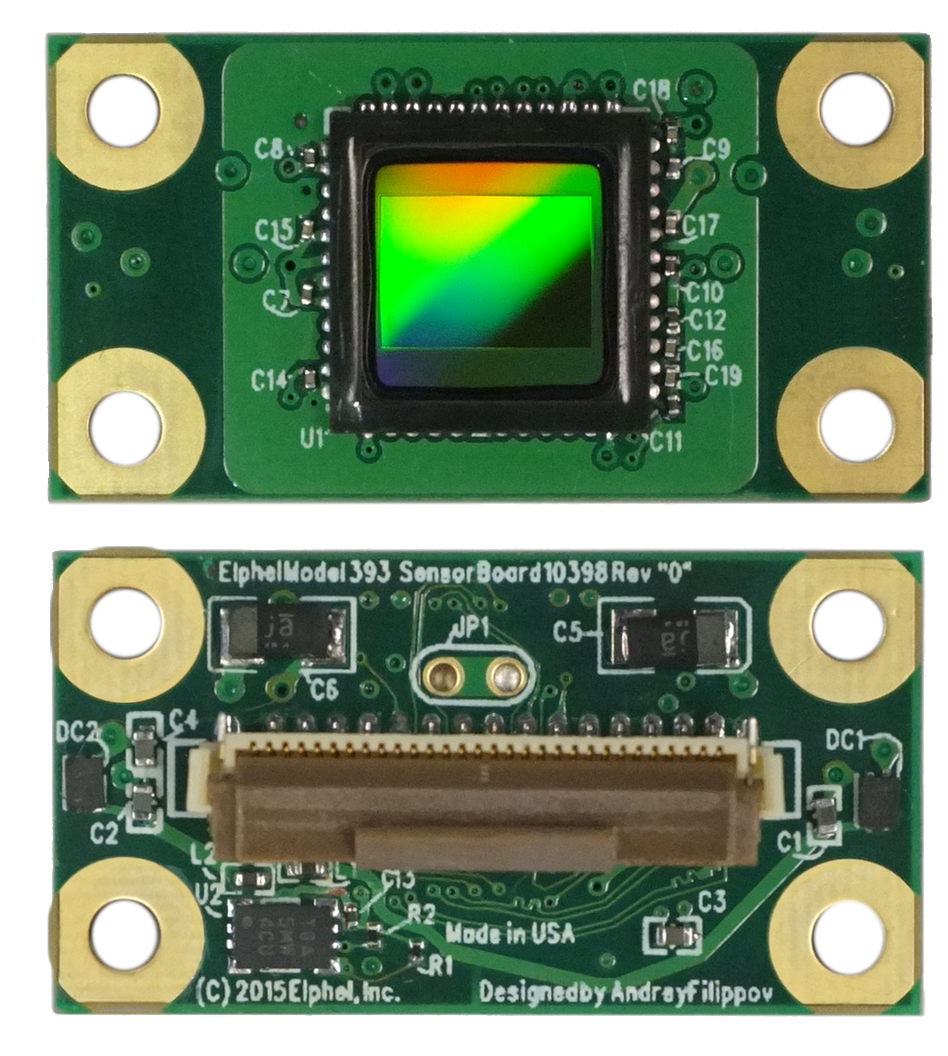
10398 Sensor Front End with 14MPix MT9F002
Sensors (ON Semiconductor MT9F002) and blank PCBs arrived in time and so I was able to hand-assemble two 10398 boards and start testing them. I had some minor problems getting data output from the first board, but it turned out to be just my bad soldering of the sensor, the second board worked immediately. To my surprise I did not have any problems with HiSPi decoder that I simulated using the sensor model I wrote myself from the documentation, so the color bar test pattern appeared almost immediately, followed by the real acquired images. I kept most of the sensor settings unmodified from the default values, just selected the correct PLL multiplier, output signal levels (1.8V HiVCM – compatible with the FPGA) and packetized format, the only other registers I had to adjust manually were exposure and color analog gains.
As it was reasonable to expect, sensitivity of the 14MPix sensor is lower than that of the 5MPix MT9P006 – our initial estimate is that it is 4 times lower, but this needs more careful measurements to find out exposure required for pixel saturation with the same illumination. Analog channel gains for both sensors we set slightly higher than minimal ones for the saturation, but such rough measurements could easily miss a factor of 1.5. MT9F002 offers more controls over the signal chain gains, but any (even analog) gain in the chain that boosts signal above the minimal needed for saturation proportionally reduces used “well capacity”, while I expect the Full Well Capacity (FWC) is already not very high for the 1.4μm x1.4 μm pixel sensor. And decrease in the number of electrons stored in a pixel accordingly increases the relative shot noise that reveals itself in the highlight areas. We will need to accurately measure FWC of the MT9F002 and have better sensitivity comparison, including that of the binned mode, but I expect to find out that 5MPix sensor are not obsolete yet and for some applications may still have advantages over the newer sensors.
 Image acquired with 5 MPix MT9P006 sensor, 1/2000 s |
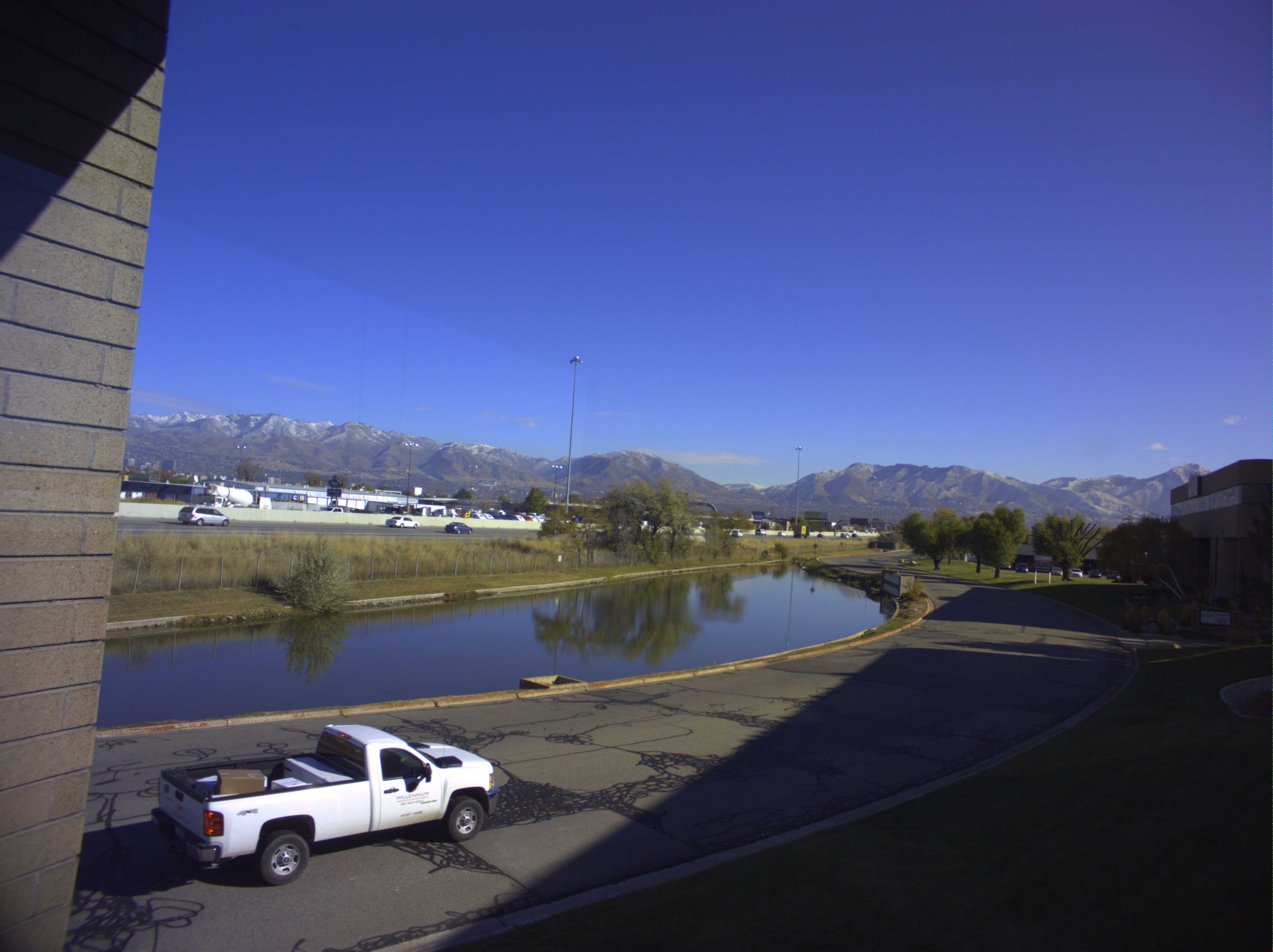 Image acquired with 14MPix MT9F002 sensor, 1/500 s |
Both sensors used identical f=4.5mm F3.0 lenses, the 5MPix one lens is precisely adjusted during calibration, the lens of the 14MPix sensor is just attached and focused by hand using the lens thread, no tilt correction was performed. Both images are saved at 100% JPEG quality (lossless compression) to eliminate compression artifacts, both used in-camera simple 3×3 demosaic algorithm. The 14 MPix image has visible checkerboard pattern caused by the difference of the 2 green values (green in red row, and green in the blue row). I’ll check that it is not caused by some FPGA code bug I might introduce (save as raw image and do de-bayer on a host computer), but it may also be caused by pixel cross-talk in the sensor. In any case it is possible to compensate or at least significantly reduce in the output data.
MT9F002 transmits data over 5 differential 100Ω pairs: 1 clock pair and 4 data lanes. For the initial tests I used our regular 70mm flex cable used for the parallel interface sensors, and just soldered 5 of 100Ω resistors to the contacts at the camera side end. It did work and I did not even have to do any timing adjustments of the differential lanes. We’ll do such adjustments in the future to get to the centers of the data windows – both the sensor and the FPGA code have provisions for that. The physical 100Ω load resistors were needed as it turned out that Xilinx Zynq has on-chip differential termination only for the 2.5V (or higher) supply voltages on the regular (not “high performance”) I/Os and this application uses 1.8V interface power – I missed this part of documentation and assumed that all the differential inputs have possibility to turn on differential termination. 660 Mbps/lane data rate is not too high and I expect that it will be possible to use short cables with no load resistors at all, adding such resistors to the 10393 board is not an option as it has to work with both serial and parallel sensor interfaces. Simultaneously we designed and placed an order for dedicated flex cables 150mm long, if that will work out we’ll try longer (450mm) controlled impedance cables.
_______________________________________________
Support-list mailing list
Support-list@support.elphel.com
http://support.elphel.com/mailman/listinfo/support-list_support.elphel.com