If you want to change your settings or unsubscribe please visit:
http://blog.elphel.com/post_notification_header/?code=cd9ad4791210eef4735d43f52cc21dd2&addr=support-list%40support.elphel.com&
3D Print Your Camera Freedom
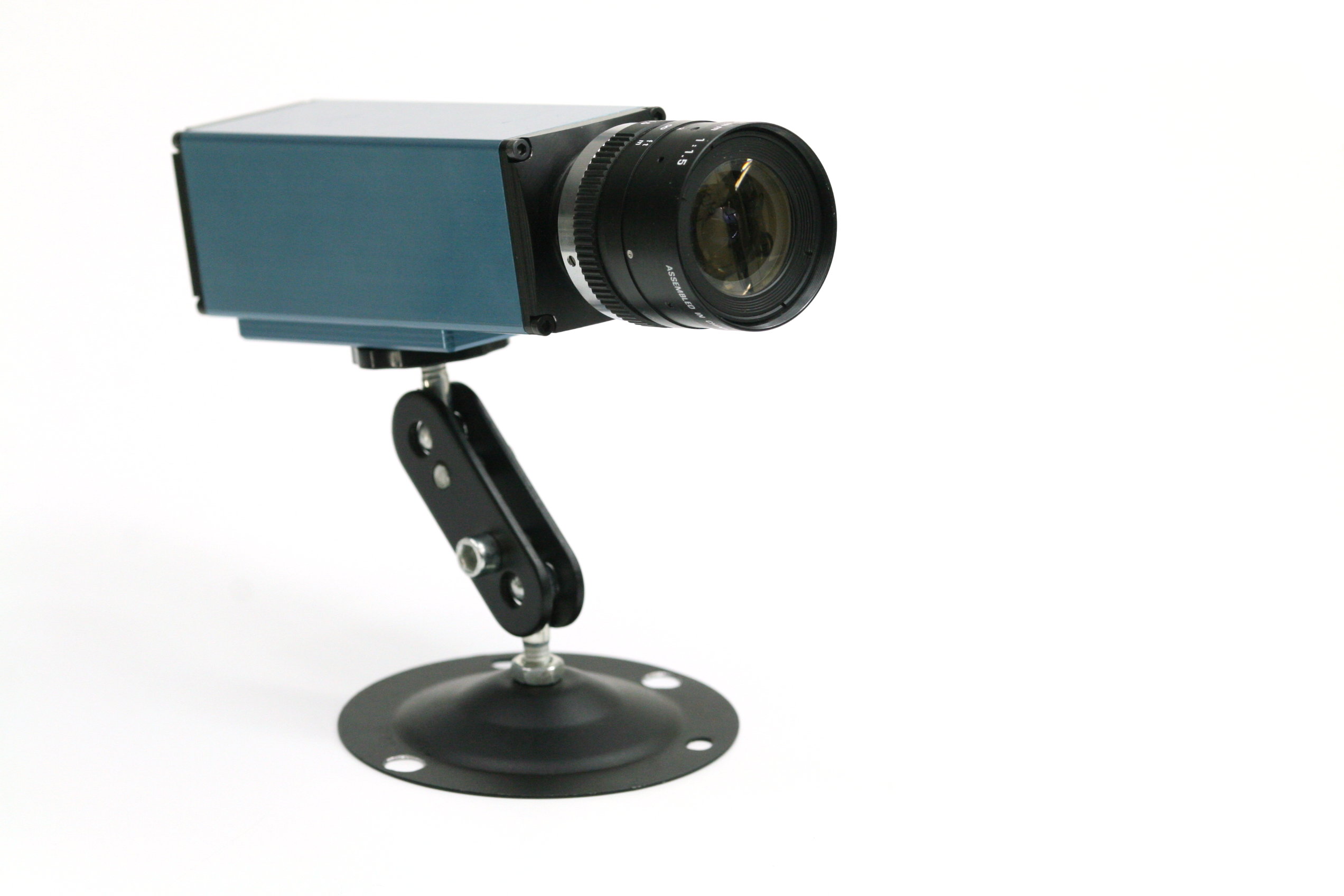
Two weeks ago we were making photos of our first production NC393 camera to post an announcement of the new product availability. We got all the mechanical parts and most of the electronic boards (14MPix version will be available shortly) and put them together. Nice looking camera, powered by a high performance SoC (dual ARM plus FPGA), packaged in a lightweight aluminum extrusion body, providing different options for various environments – indoors, outdoors, on board of the UAV or even in the open space with no air (cooling is important when you run most of the FPGA resources at full speed). Tons of potential possibilities, but the finished camera did not seem too exciting – there are so many similar looking devices available.
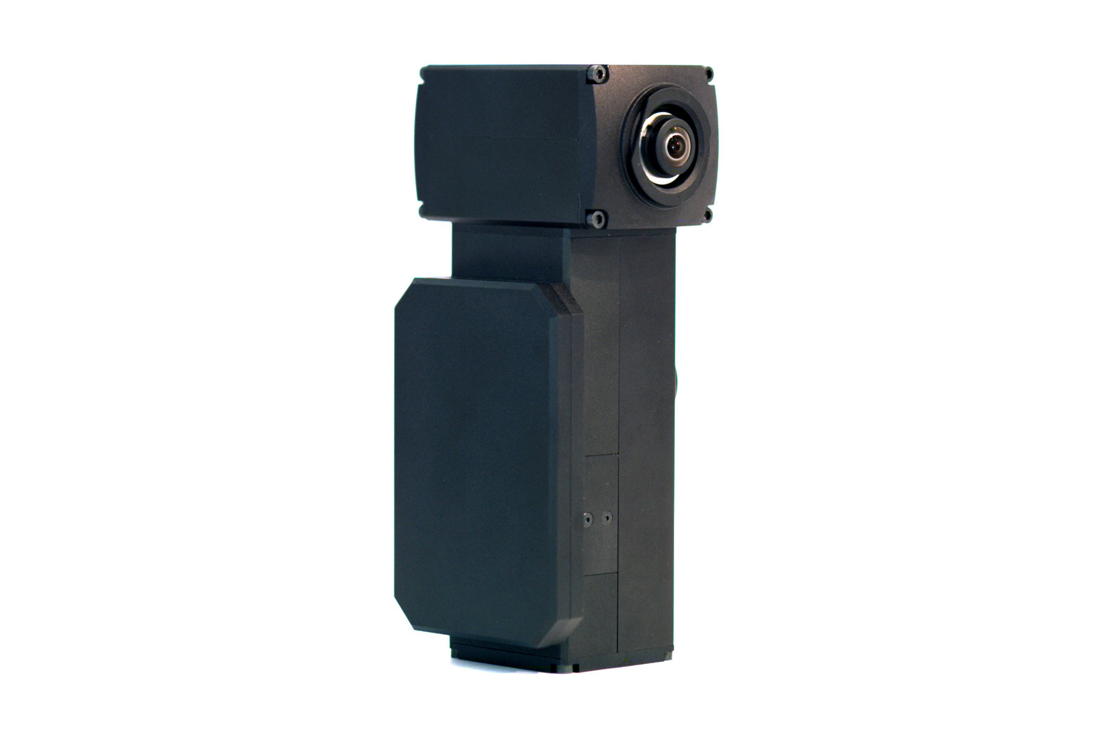
NC393 camera, back panel view. Includes DC power input (12-36V and 20-75V options), GigE, microSD card (bootable), microUSB(type B) connector for a system console with reset and boot source selection, USB/eSATA combo connector, microUSB(type A) and 2.5mm 4-contact barrel connector for external synchronization I/O
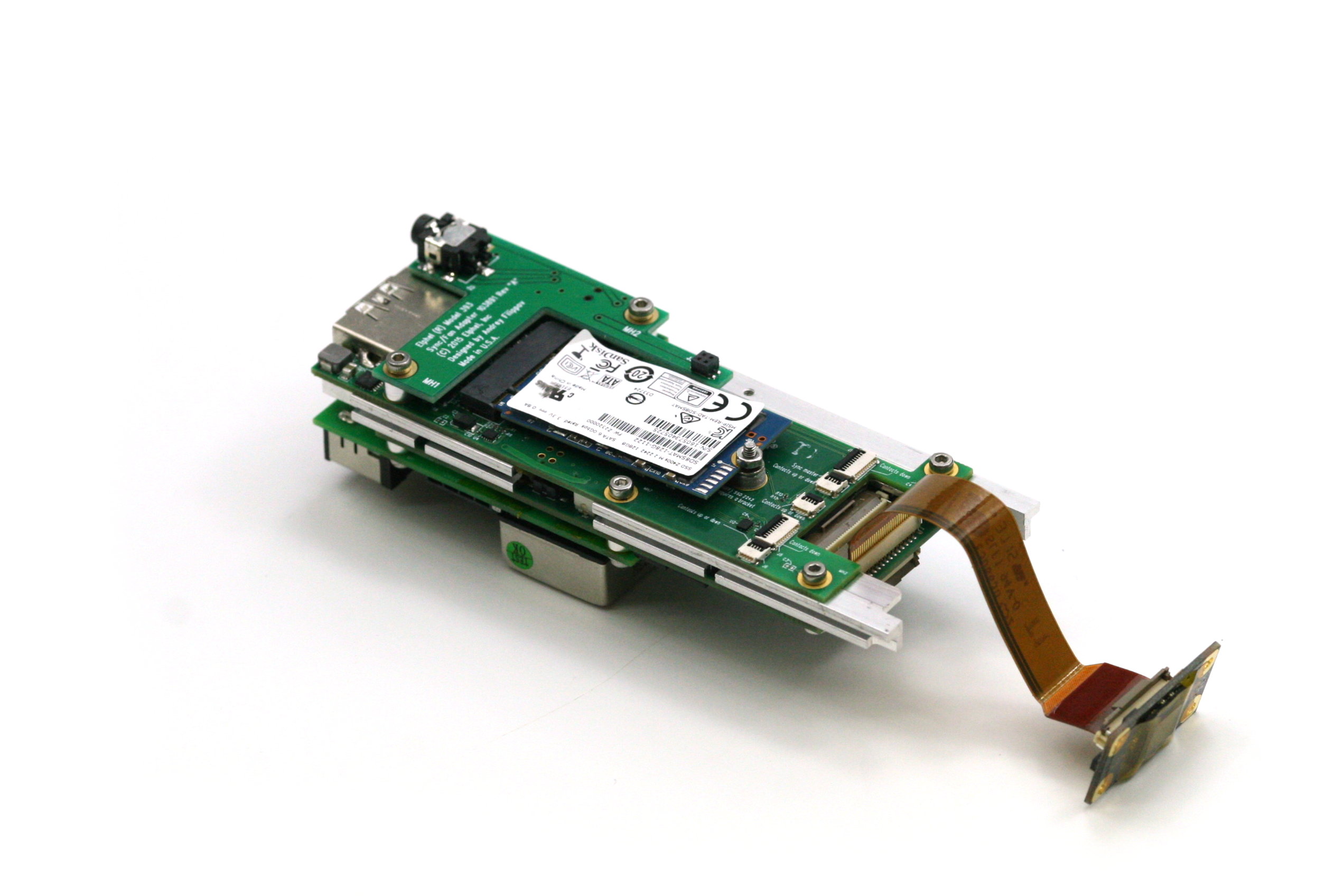
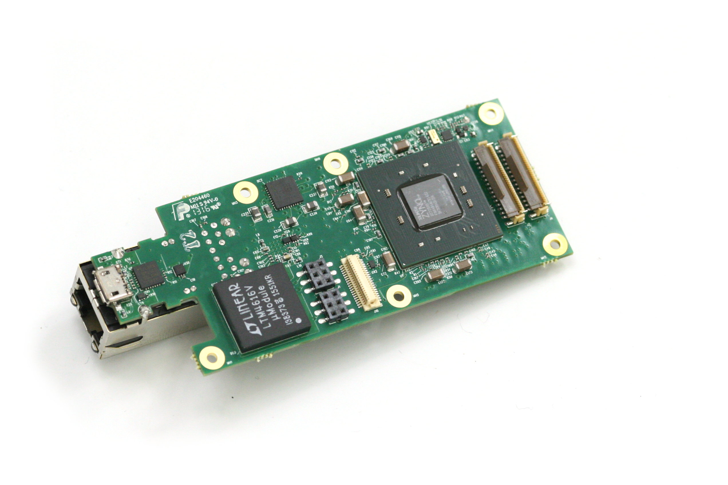
NC393 assembled boards: 10393(system board), 10385 (power supply board), 10389(interface board), 10338e (sensor board) and 103891 - synchronization adapter board, view from 10389. m.2 2242 SSD shown, bracket for the 2260 format provided. 10389 internal connectors include inter-camera synchronization and two of 3.3VDC+5.0VDC+I2C+USB ones.
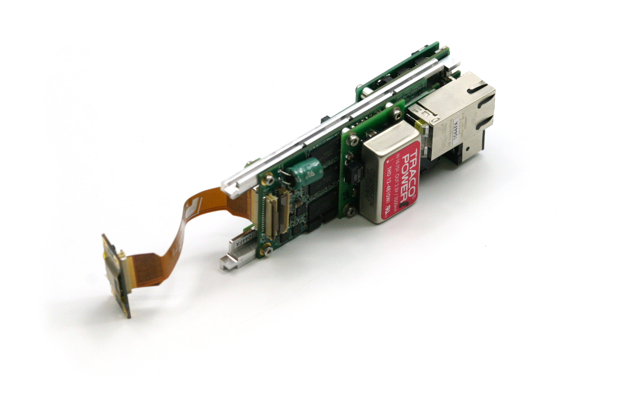
NC393 assembled boards: 10393(system board), 10385 (power supply board), 10389(interface board), 10338e (sensor board) and 103891 - synchronization adapter board, view from 10385
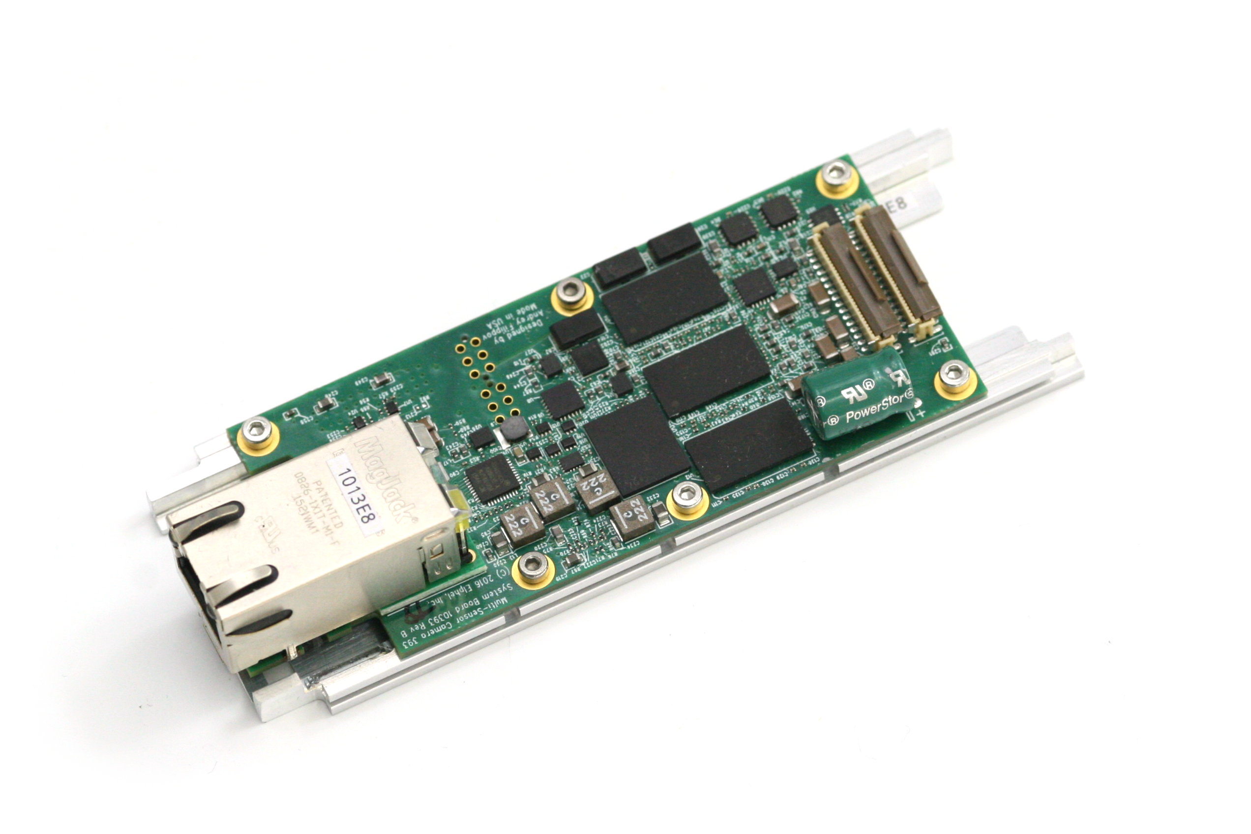
10393 system board attached to the heat frame, view from the heat frame. There is a large aluminum heat spreader attached to the other side of the frame with thermal conductive epoxy that provides heat transfer from the CPU without the use of any spring load. Other heat dissipating components use heat pads.
An obvious reason for our dissatisfaction is that the single-sensor camera uses just one of four available sensor ports. Of course it is possible to use more of the freed FPGA resources for a single image processing, but it is not what you can use out of the box. Many of our users buy camera components and arrange them in their custom setup themselves – that does not have a single-sensor limitation and it matches our goals – make it easy to develop a custom system, or sculpture the camera to meet your ideas as stated on our web site. We would like to open the cameras to those who do not have capabilities of advanced mechanical design and manufacturing or just want to try new camera ideas immediately after receiving the product.
Why multisensor?
One simple answer can be “because we can” – the CPU+FPGA based camera system can simultaneously handle multiple small image sensors we love – sensors perfected by the cellphone industry. Of course it is also possible to connect one large (high resolution/high FPS) sensor or even to use multiple camera system for one really fast sensor – we did such trick with the NC323 camera for book scanning, but we believe that the future is with the multiple view systems that combine images from several synchronized cameras using computational photography rather than large lens/large sensor traditional cameras.
Multi-sensor systems can acquire high-resolution panoramic images in a single shot (or offer full sphere live video), they can be used for image-based 3-d reconstruction that in many cases provide much superior quality to the now traditional LIDAR-based scanners which can not output cinematographic quality 3-d scenes. They can be used to capture HDR video by combining data for the same voxels rather than pixels. Such systems can easily beat the shallow depth of field of the traditional large format cameras and offer possibility of the post-production focus distance adjustment. Applications are virtually endless, and while at Elphel we are developing such multi-sensor systems our main products are still the high-performance camera systems hackable at any imaginable level.
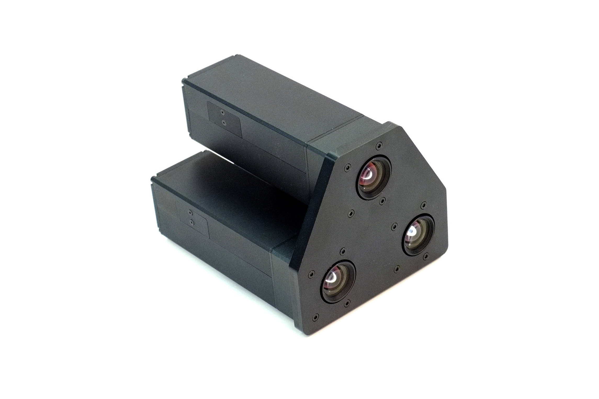
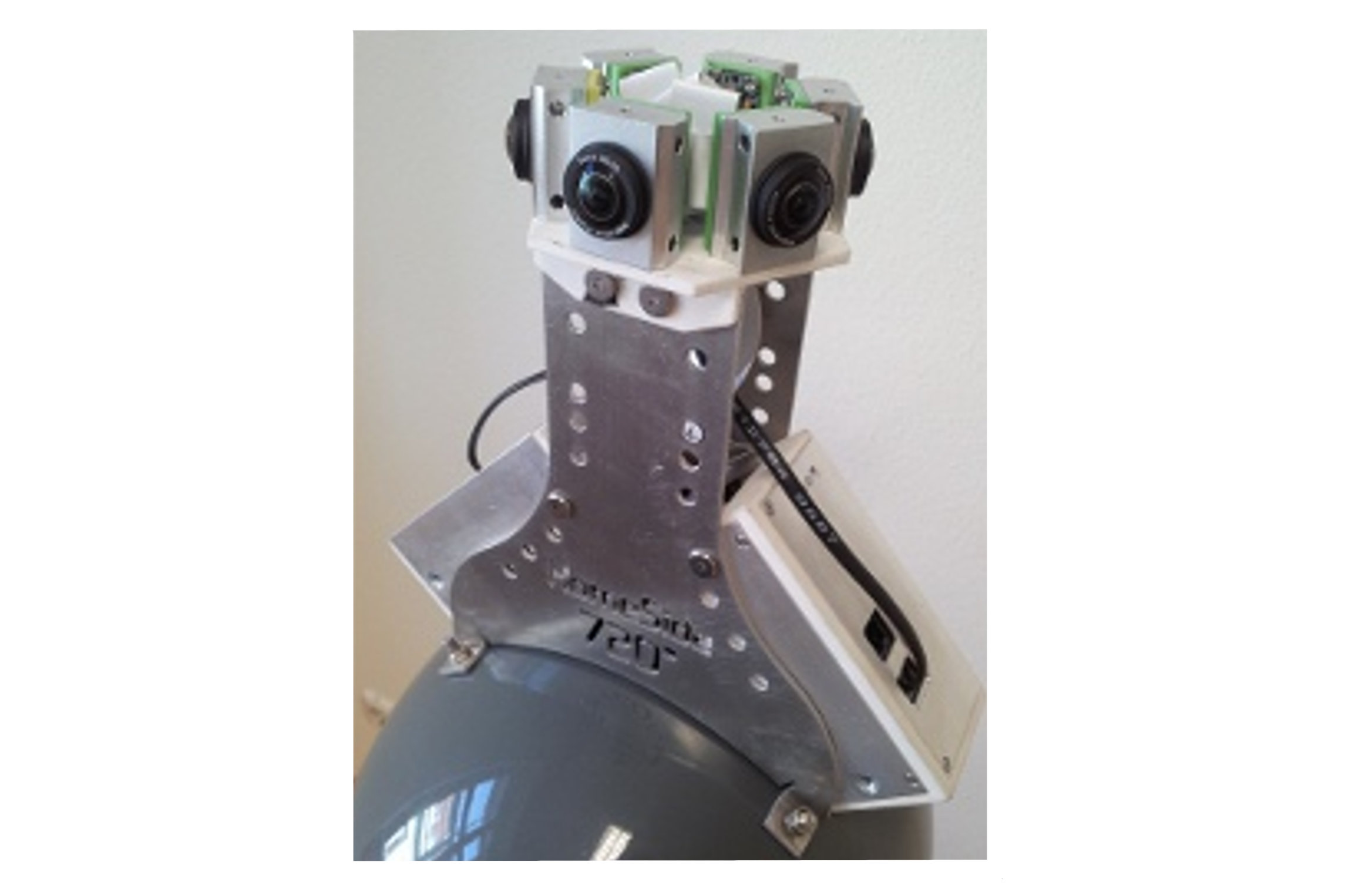
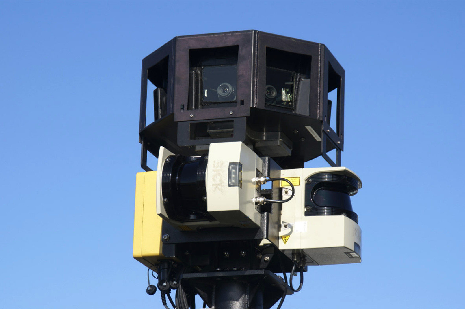
NC353-369-PHG3 3-sensor camera camera, view demo (mouse scroll changes disparity, shift-scroll - zoom)
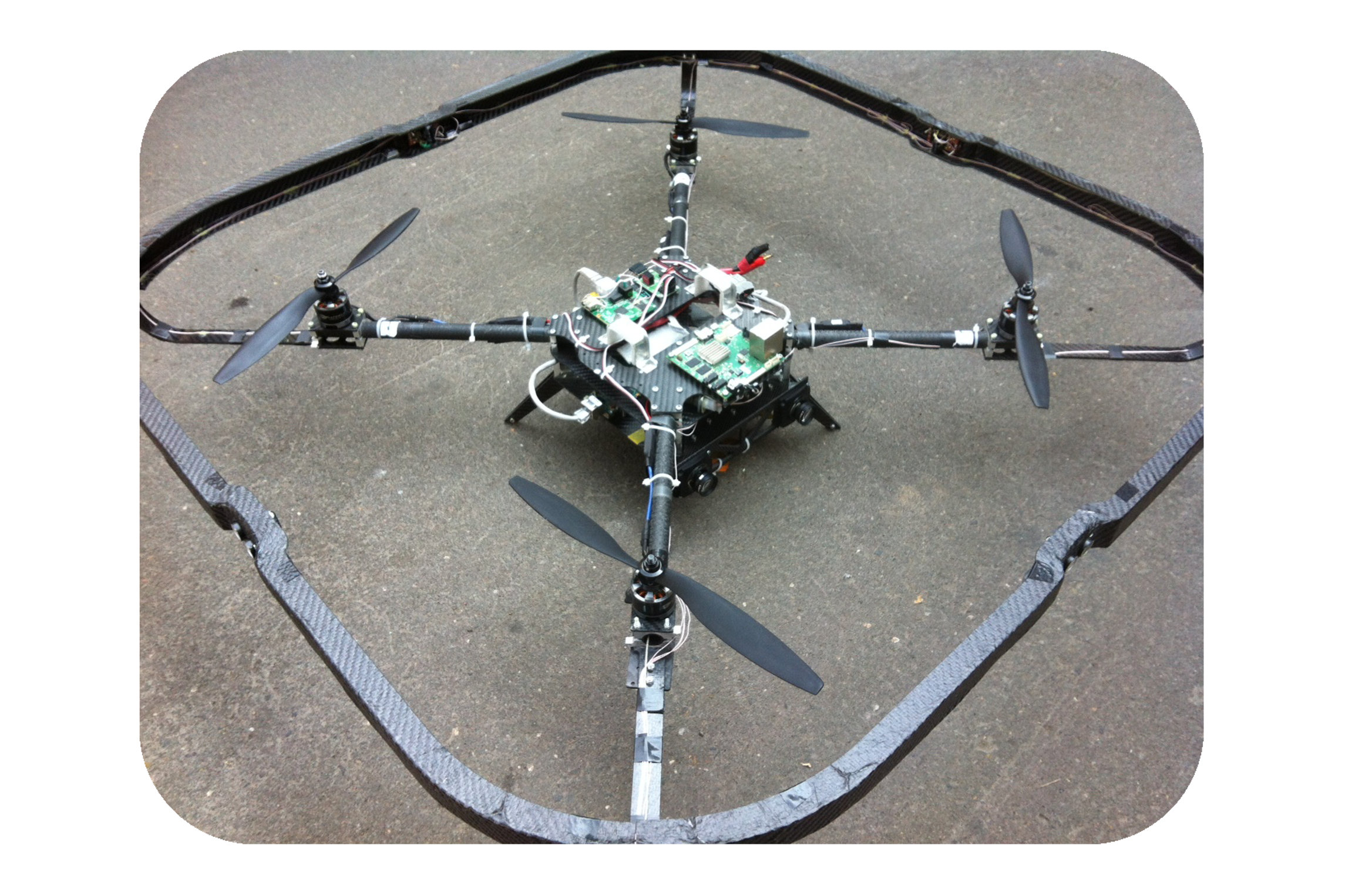
Quadcopter using multisensor camera for navigation, by 'Autonomous Aerospace' team in Krasnoyarsk, Russia
Hackable by Design
To have all documentation open and released under free licenses such as GNU GPL and CERN OHL is a precondition, but it is not sufficient. The hackable products must be designed to be used that way and we strive to provide this functionality to our users. This is true for the products themselves and for the required tools, so we had to go as far as to develop software for FPGA tools integration with the popular Eclipse IDE and replace closed source manufacturer code that is not compatible with the free software Verilog simulators.
Same is true for the camera mechanical parts – users need to be able to reconfigure not just the firmware, FPGA code or rearrange the electronic components, but to change the physical layout of their systems. One popular solution to this challenge is to offer modular camera systems, but unfortunately this approach has its limits. It is similar to Lego® sets (where kids can assemble just one object already designed by the manufacturer) vs. Lego® bricks where the possibilities are limited by the imagination only. Often camera modularity is more about marketing (suggesting that you can start with a basic less expensive set and later buy more parts) than about the real user freedom.
We too provide modular components and try to maintain compatibility between the generations of modules – new Elphel cameras can directly interface more than a decade old sensor boards and this does not prevent them from simultaneously supporting modern sensor interfaces. Physical dimensions and shapes of the camera electronic boards also remain the same – they just pack more performance in the same volume as newer components become available. Being in the business of developing hackable cameras for 15 years, we realize that the modularity alone is not a magic bullet. Luckily now there are other possibilities.
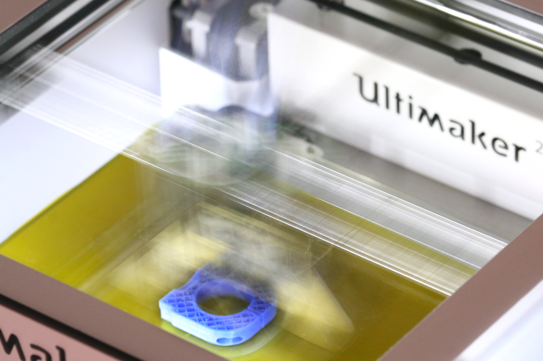
3d printing camera parts
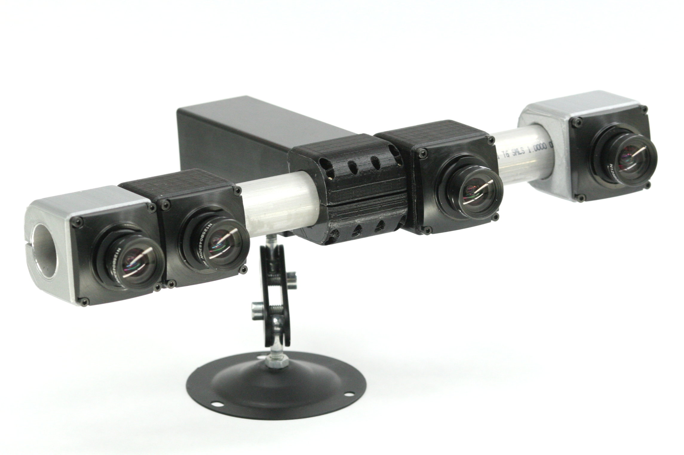
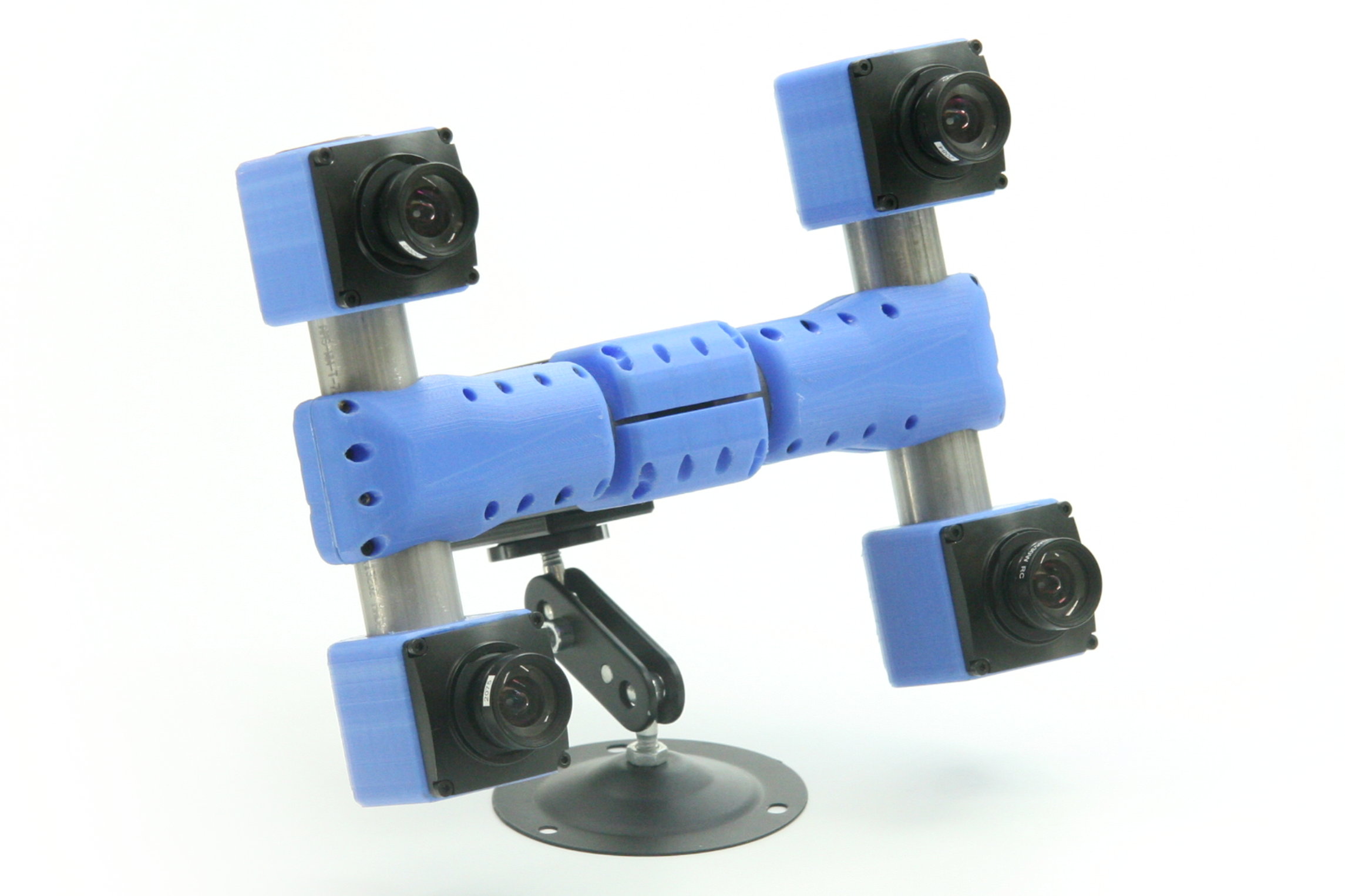
3d printing process offers freedom in the material world but so far we were pessimistic about its use for the camera components where microns often matter. Some of the camera modules use invar (metal alloy that has almost zero thermal expansion coefficient at normal temperatures) elements to compensate for the thermal expansion, and the PLA plastic parts seem rather alien here. Nevertheless it is possible to meet the requirements of the camera mechanical design even with this material. In some cases it is sufficient to have precise and stable sensor/lens combination – sensor front end (SFE), small fluctuations in the mutual position/orientation of the individual SFE may be compensated using image data itself in the overlapping areas. It is possible to design composite structure that combines metal elements of simple shape (such as aluminum, thin wall stainless steel tubes or even small diameter invar rods) and printed elements of complex shape. Modern fiber-reinforced material for 3d-printing promise to improve mechanical stability and reduce thermal expansion of the finished parts.
This technology perfectly fits to the hackable multi-sensor systems and fills important missing part of “sculpturing” the user camera. 3-d printing is slow and we can not print every camera, but that is not really needed. While we certainly can print some parts, we are counting that this technology is now available in most parts of the world where we ship the products, and the parts can be manufactured by the end user. We anticipate that many of the customer designs being experimental by nature will need later modifications, building the parts by the user can save on the overseas shipments too.
We count that the users will design their own parts, but we will try to make their job easier and provide modifiable design examples and fragments that can be used in their parts. This idea of incorporating 3-d printing technology into Elphel products is just 2 weeks old and we prepared several quick design prototypes to try it – below are some examples of our first generation of such camera parts.
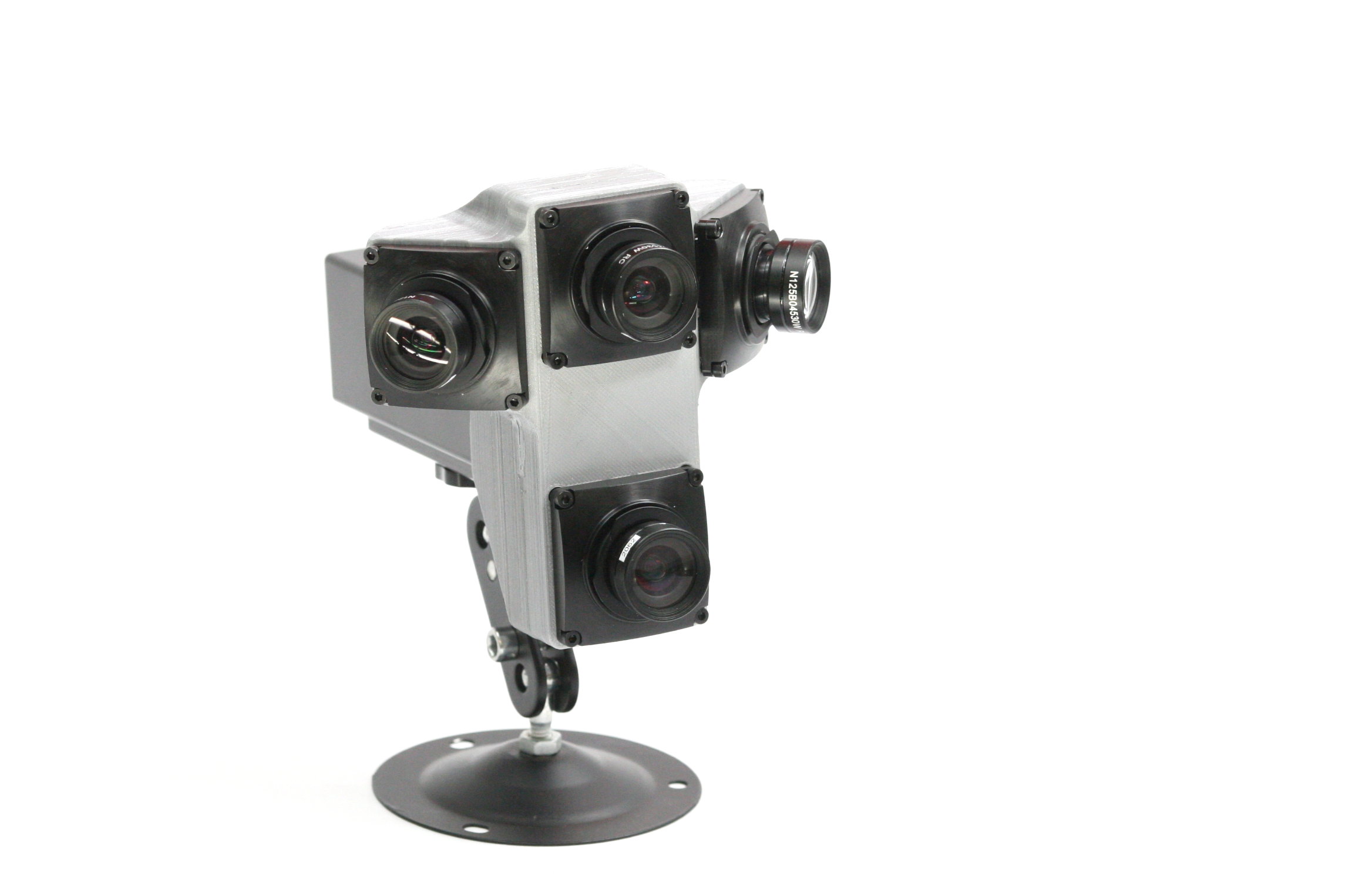
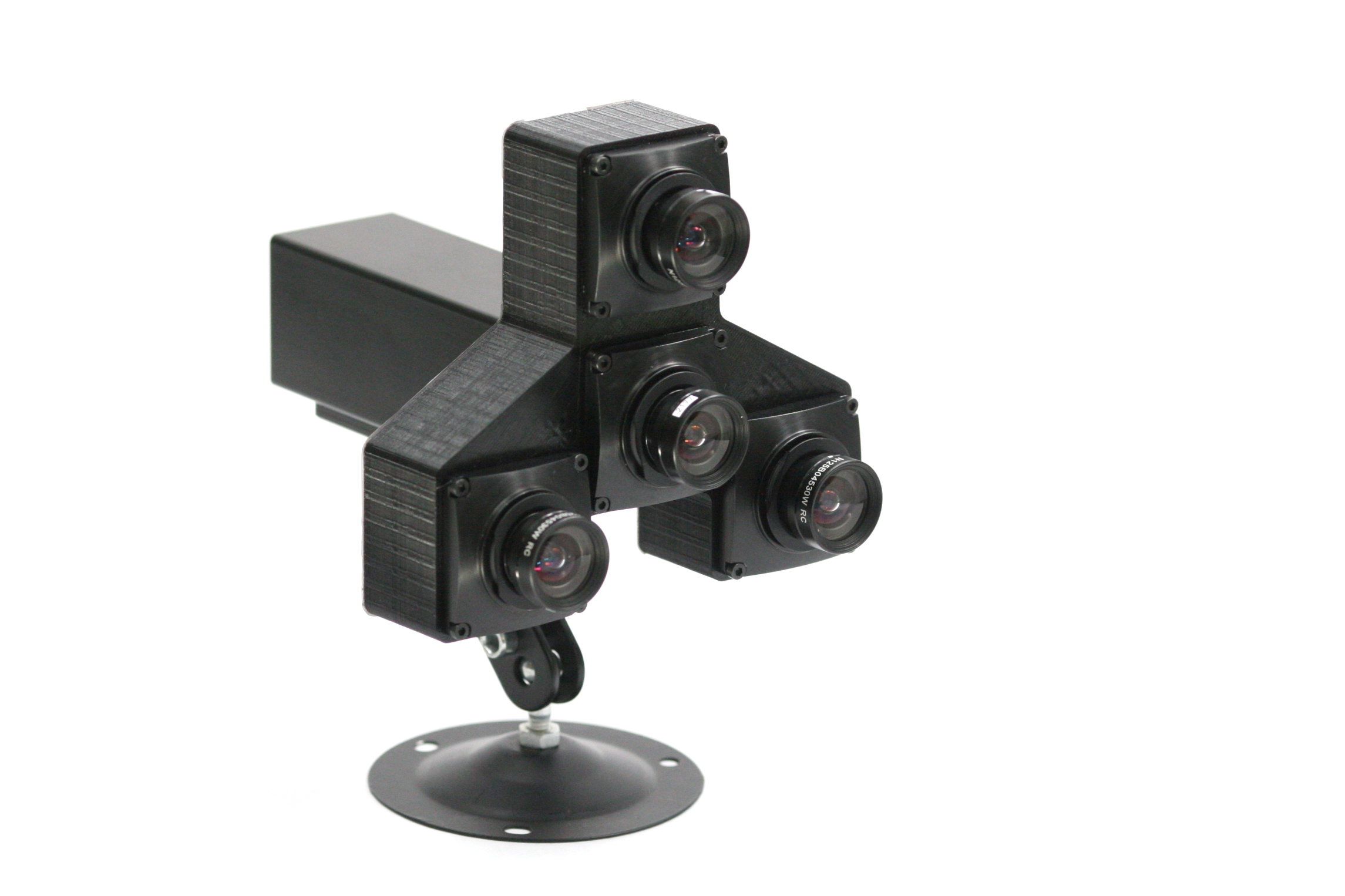
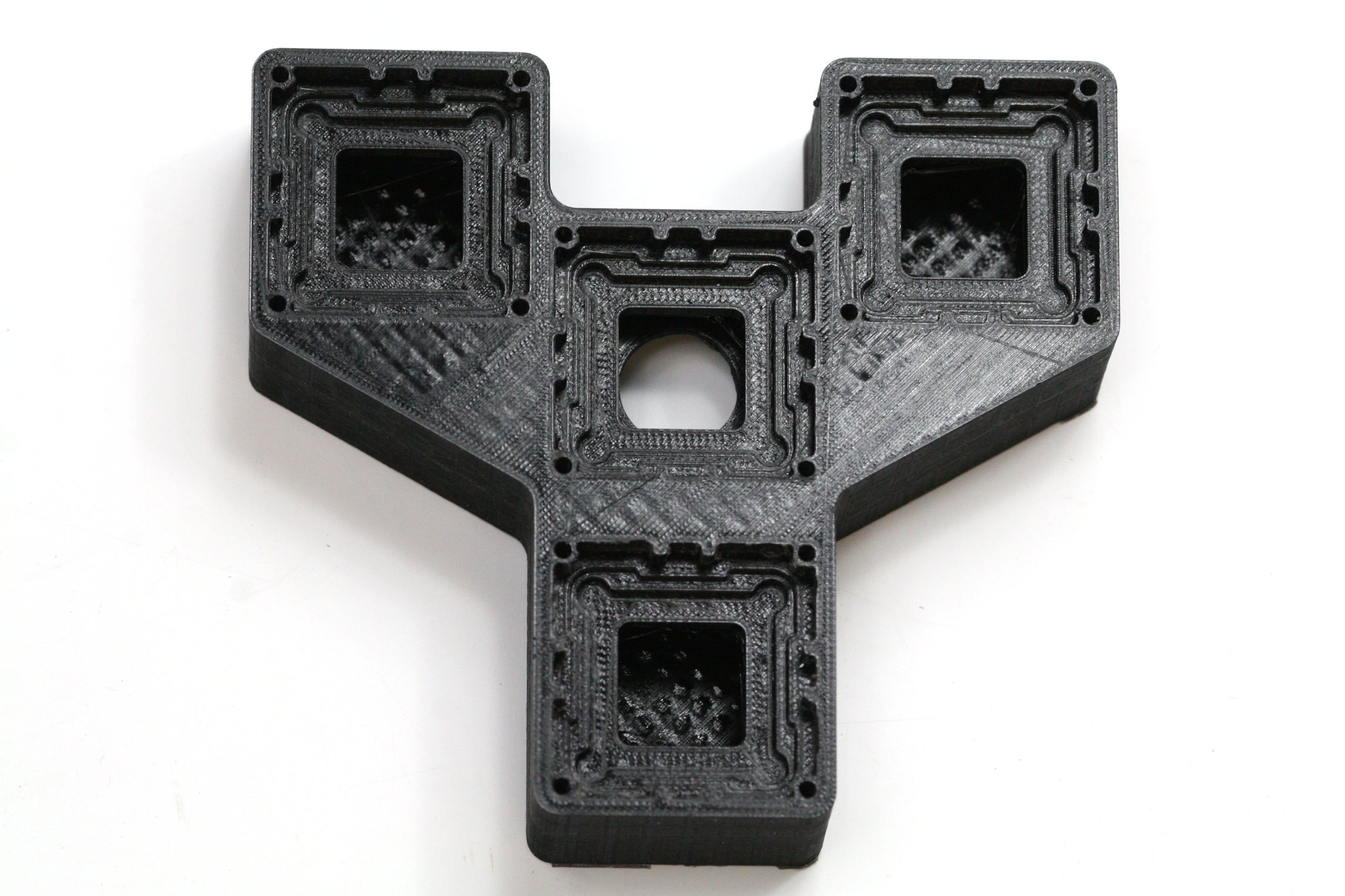
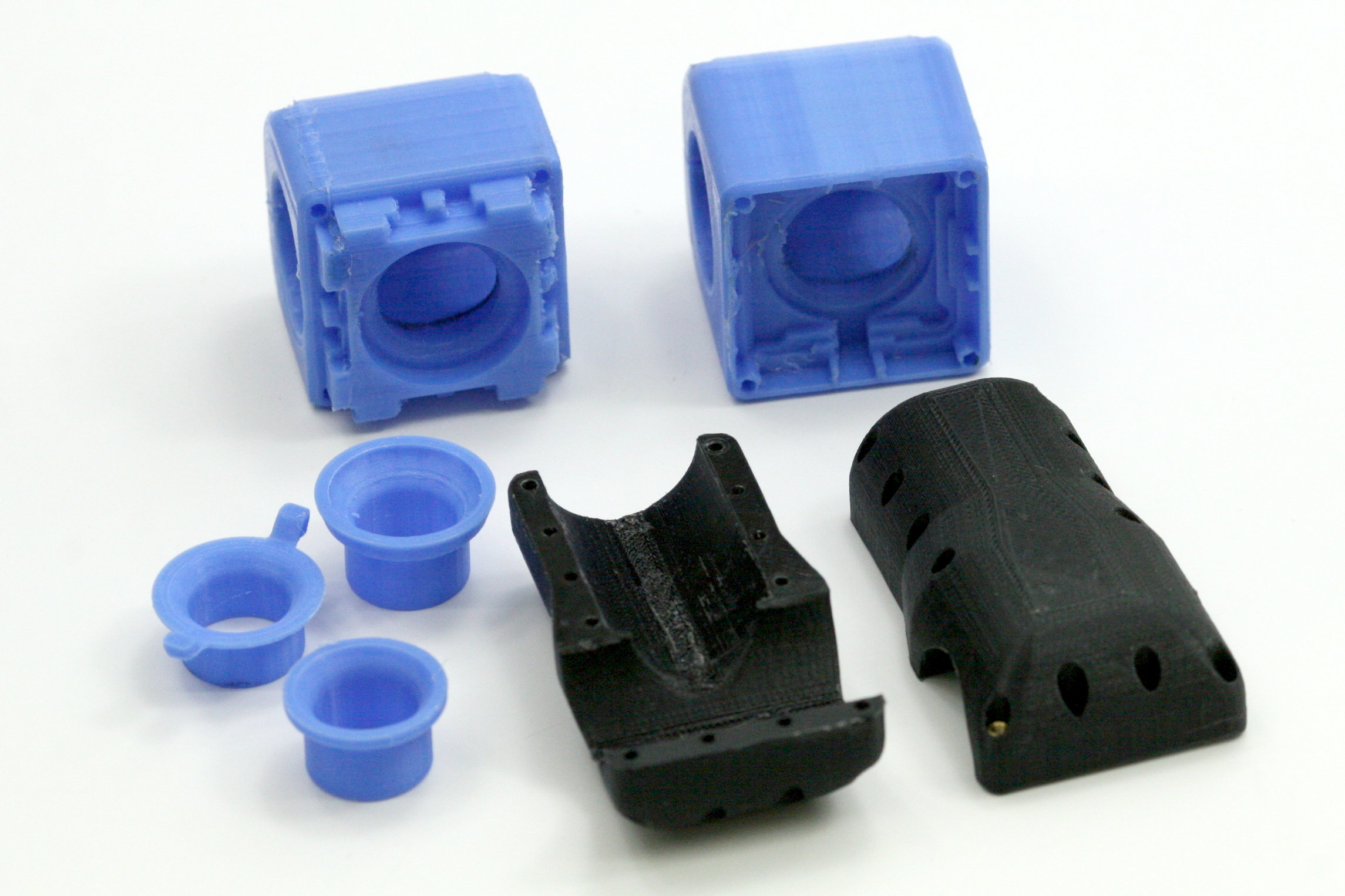
Deliverables
“3d print your camera freedom” – we really mean that. It is not about printing of a camera or its body. You can always get a complete camera in one of the available configurations packaged in a traditional all-metal body if it matches your ideas, printing just adds freedom to the mechanical design.
We will continue to provide all the spectrum of the camera components such as assembled boards and sensor front ends as well as the complete cameras in multiple configurations. For the 3-d printed versions we will have the models and reusable design fragments posted online. We will be able to print some parts and ship the factory assembled cameras. In some cases we may be able to help with the mechanical design, but we try to avoid doing any custom design ourselves. We consider our job is done well if we are not needed to modify anything for the end user. Currently we use one of the proprietary mechanical CAD programs so we do not have fully editable models and can only provide exported STEP files of the complete parts and interface fragments that can be incorporated in the user designs.
We would like to learn how to do this in FreeCAD – then it will be possible to provide the usable source files and detailed instructions how to customize them. FreeCAD environment can be used to create custom generator scripts in Python – this powerful feature helped us to convert all our mechanical design files into x3d models that can be viewed and navigated in the browser (video tutorial). This web based system proved to be not just a good presentation tool but to be more convenient for parts navigation than the CAD program itself, we use it ourselves regularly for that purpose.
Maybe we’ll be able to find somebody who is both experienced in mechanical design in FreeCAD and interested in multi-sensor camera systems to cooperate on this project?
_______________________________________________
Support-list mailing list
Support-list@support.elphel.com
http://support.elphel.com/mailman/listinfo/support-list_support.elphel.com