To repeat an earlier comment, try a load resistor on the output leads,
say 5K or something in that range at least 20 watts and 50 watts would
be ideal for full power tests. Pull the 6146 and the osc tubes to get
rid of the RF. You have to have a load on the mod iron to keep things
under control.
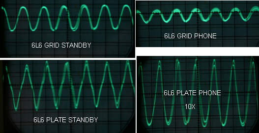
The waveform that is puzzling is the 6L6 in standby. What is the
amplitude? Looks like we have a parasitic oscillation in the amp
circuit and it could still be there mixed in with the audio on xmit.
There is hum too as it is showing up as a variation in the peak
amplitude of the 500 Hz wave.
You'll have to put back the bypass caps to gain some control over the RF
getting into the audio. Maybe a few RF chokes in the audio lines to
eliminate the RF. As you have seen. sticking the scope probe into a
medium or low impedance is OK usually. But a high impedance like the
6L6 grid introduces more errors. Another antenna.
Larry


Jack Schmidling wrote:
I did some more sig tracing and came up with some pics of where the
trouble seems to be.
Putting a 500 hz sine wave into the mic input, I see a nice sine wave
until I get to the modulator tubes.
The grid in standby looks close enough but when I go to phone mode it
gets flaky.
The plates look really flaky in standby but look more normal in phone
mode but there seems to be a bunch of waves competing for the space.
I posted some pics to http://schmidling.com/mod.jpg

Comments eagerly awaited....

js
______________________________________________________________
AMRadio mailing list
List Home: http://mailman.qth.net/mailman/listinfo/amradio
Partner Website: http://www.amfone.net
Help: http://mailman.qth.net/mmfaq.html
Post: mailto:[email protected]