Hello Phil,

As I encountered the same behaviour as yours when switching to kernel 4.4,
I resolved mine with the cape_universal (the default with the official
image provided) with a line 'config-pin P9_14 pwm' for the PWM1A for ex.
But, the numbering of the PWMs differ at each booting of the bbb ! not very
easy to handle, so after I saw the PWM with npwm == 2 are not the ECAP ones
, I wrote this :
import os
import glob
from collections import OrderedDict
from pprint import pprint
os.chdir('/sys/class/pwm/')
chips = glob.glob('pwmchip*')
pwms = ['PWM0A', 'PWM0B', 'PWM1A', 'PWM1B', 'PWM2A', 'PWM2B']
nbpwm = 0
pwm_dict = OrderedDict()
for chip in chips:
npwm = int(open('{}/npwm'.format(chip)).read())
if npwm == 2:
for i in [0, 1]:
path = '/sys/class/pwm/{}/'.format(chip)
open(path+'export', 'w').write(str(i))
pwm_dict[pwms[nbpwm+i]] = '{}/pwm{}/'.format(path, i)
nbpwm += 2
pprint(pwm_dict)
which wil give for ex. :
root@beaglebone:~# ./PWM_4.4.py
{'PWM0A': '/sys/class/pwm/pwmchip0//pwm0/',
'PWM0B': '/sys/class/pwm/pwmchip0//pwm1/',
'PWM1A': '/sys/class/pwm/pwmchip2//pwm0/',
'PWM1B': '/sys/class/pwm/pwmchip2//pwm1/',
'PWM2A': '/sys/class/pwm/pwmchip4//pwm0/',
'PWM2B': '/sys/class/pwm/pwmchip4//pwm1/'}
*root@beaglebone**:~**# config-pin P9_14 pwm*
root@beaglebone:~# cd /sys/class/pwm/pwmchip2/pwm0/
root@beaglebone:/sys/class/pwm/pwmchip2/pwm0# ls
duty_cycle enable period polarity power uevent
root@beaglebone:/sys/class/pwm/pwmchip2/pwm0# echo 1000000 > period
root@beaglebone:/sys/class/pwm/pwmchip2/pwm0# echo 200000 > duty_cycle
root@beaglebone:/sys/class/pwm/pwmchip2/pwm0# echo 1 > enable
and I got the correct PWM on my oscilloscope, hope it helps, good luck !
Samuel
Le jeudi 28 juillet 2016 13:13:57 UTC+2, [email protected] a écrit :
>
> Hello William,
>
> the output is:
> root@beaglebone:/lib/firmware# ls /sys/devices/platform/ocp/
> 40300000.ocmcram 47400000.usb 48046000.timer 4819c000.i2c
> 48302000.epwmss 4a100000.ethernet modalias
> ocp:P9_22_pinmux
> 40302000.ocmcram_nocache 48022000.serial 48048000.timer 481a0000.spi
> 48304000.epwmss 4a300000.pruss ocp:l4_wkup@44c00000
> of_node
> 44e07000.gpio 48030000.spi 4804a000.timer
> 481aa000.serial 48310000.rng 4c000000.emif
> ocp:P8_13_pinmux
> power
> 44e09000.serial 48038000.mcasp 4804c000.gpio
> 481ac000.gpio 49000000.edma 53100000.sham
> ocp:P8_19_pinmux
> subsystem
> 44e0b000.i2c 4803c000.mcasp 48060000.mmc
> 481ae000.gpio 49800000.tptc 53500000.aes
> ocp:P9_14_pinmux
> uevent
> 44e35000.wdt 48042000.timer 480c8000.mailbox
> 48200000.interrupt-controller 49900000.tptc 56000000.sgx ocp:
> P9_16_pinmux
> 44e3e000.rtc 48044000.timer 480ca000.spinlock
> 48300000.epwmss 49a00000.tptc driver_override ocp:
> P9_21_pinmux
>
> I compiled your overlay with this command:
> dtc -O dtb -o /lib/firmware/univ-wph-00A0.dtbo -b 0 -@ /lib/firmware/univ-
> wph-00A0.dts
> Is that the correct way to do it?
>
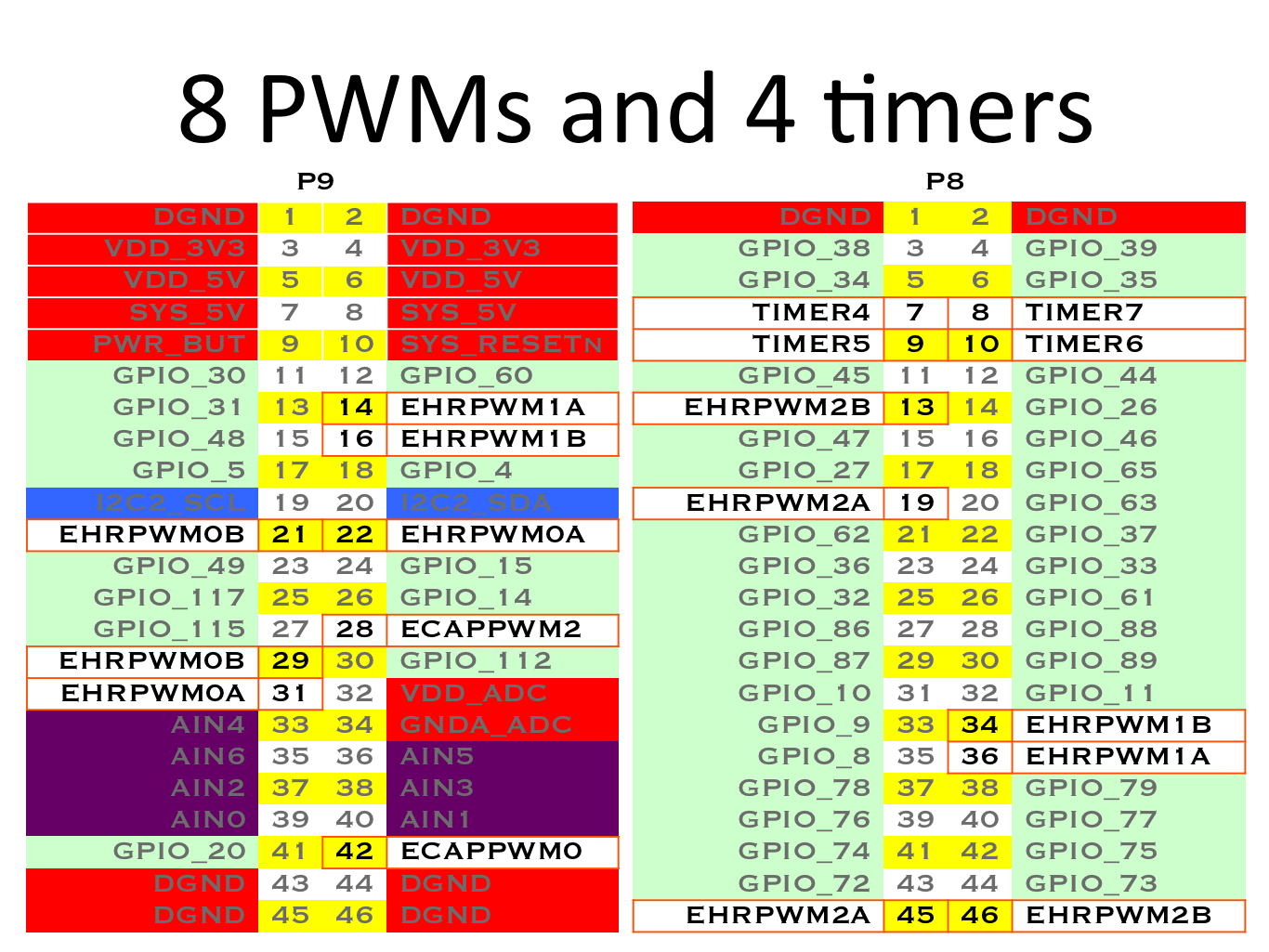
> Regarding your question whether I used the correct pins: I set all pwm
> outputs with the nested for commands described in the my last post and used
> the oscilloscope to measure all the pwm pins given in this image (
> http://beagleboard.org/static/images/cape-headers-pwm.png) against a GND
> pin. So at least one of them should have caused some output on the
> oscilloscope.
> The oscilloscope is working correctly as it gives me 3.3V and 5V for P9_3
> and P9_5.
>
> Best regards
> Phil
>
>
>
>
--
For more options, visit http://beagleboard.org/discuss
---
You received this message because you are subscribed to the Google Groups
"BeagleBoard" group.
To unsubscribe from this group and stop receiving emails from it, send an email
to [email protected].
To view this discussion on the web visit
https://groups.google.com/d/msgid/beagleboard/1b96f441-46af-4a4d-b975-657e3218775e%40googlegroups.com.
For more options, visit https://groups.google.com/d/optout.