The Densitron DMT040QBHTNT0-1A data sheet has much useful info.
DE Mode:
VS and HS are inverted (active low)
DE and DOTCLK (active-high)
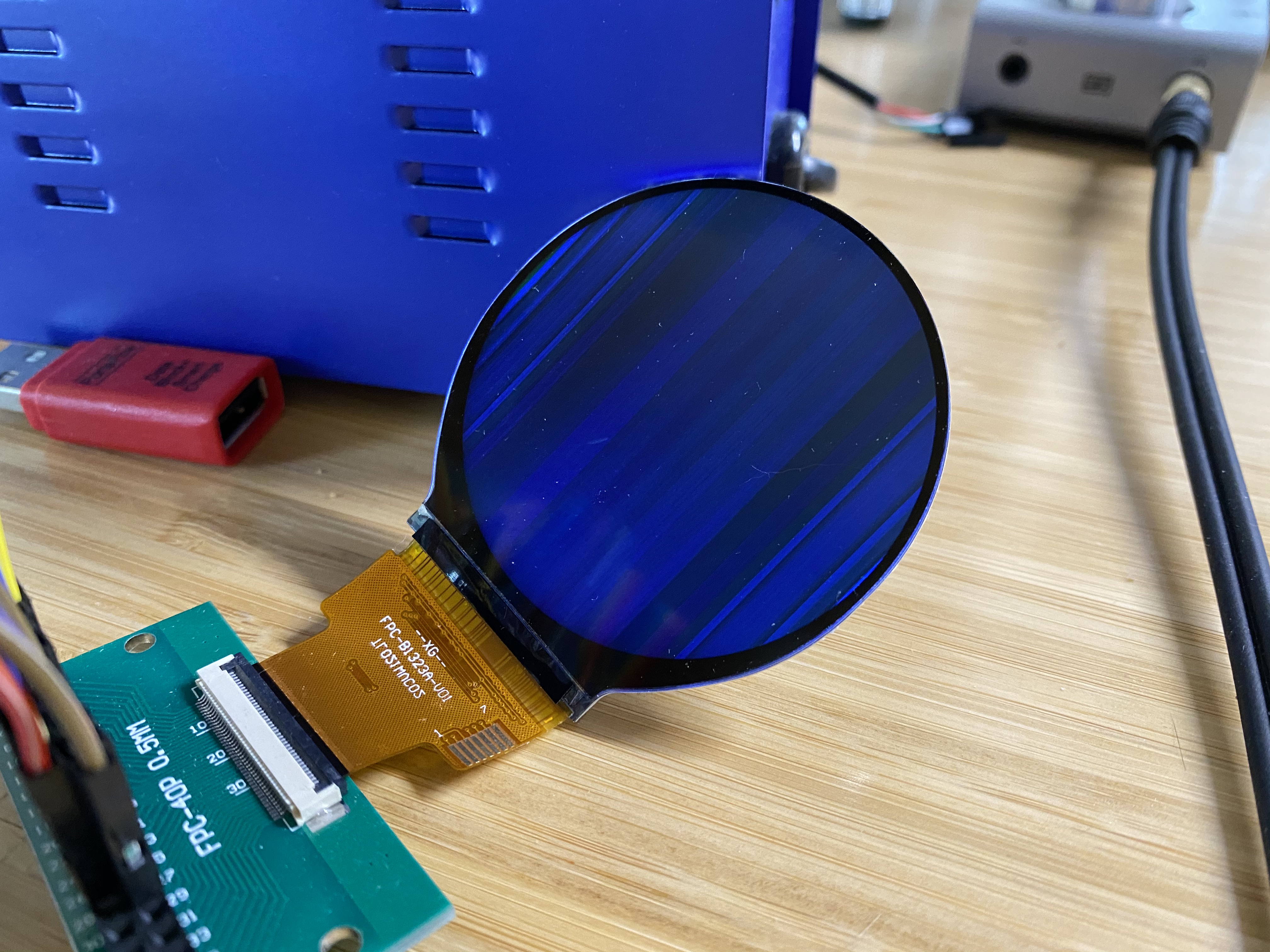
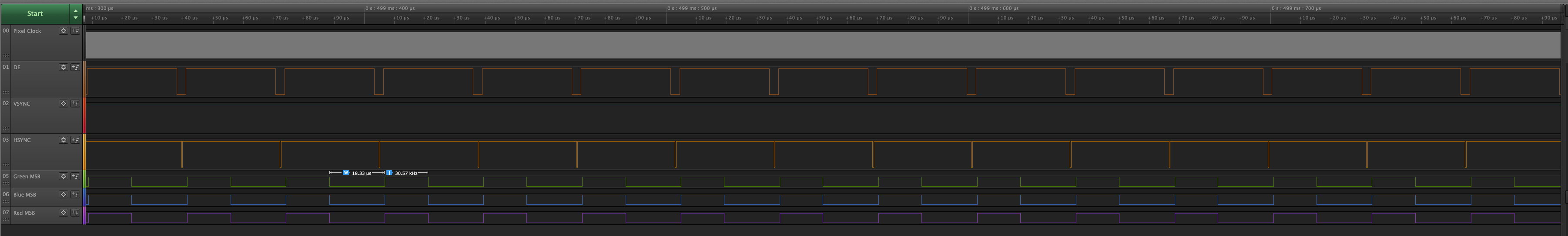
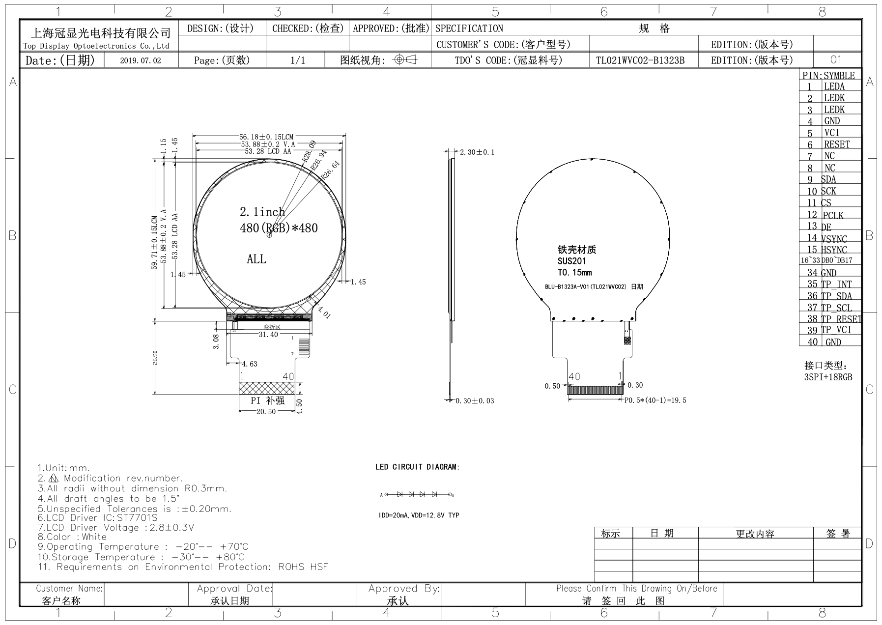
HV Mode:
VS and HS are active-low
PCLK active-high
DE always 1

SPI:
SPI has 4 clock modes
SCK/SCL is active-high (normally low on fall of active-low CS)
clocks data in on first rising edge
clocks data out on first falling edge after first rising edge


On Monday, 30 March 2020 22:34:30 UTC+1, Corey Vixie wrote:
>
> Hi folks. For some months now, I've been trying to get a small LCD based
> on the Sitronix ST7701S working with the BeagleBone Black. Because the
> Linux kernel only includes a MIPI DSI driver for the ST7701 (which is
> similar but not identical), I wrote my own SPI driver in Rust. It's
> open-source, available here:
> https://github.com/ironblock/ST7701S-SPI-Driver
>
> My problem is that no matter what kind of image I try and display, the
> output is garbled. I see no distinct pixel color values across an entire
> column (or maybe they're lines? I'm not sure which way is up).
>
> I've connected it using the 16-bit pinmux, since that seemed "safest". My
> SPI commands work, and doing things like "turn all pixels on", "turn all
> pixels off", "invert colors", etc. all work as expected, but the image is
> never clear.
>
> I put 33R resistors on the data lines in case there was some kind of
> reflection or interference that was causing the problem.
>
> I'm currently powering the LCD driver from P9.3 (VDD 3.3v). The Sitronix
> data sheet indicates that this is allowed, but the LCD vendor's data sheet
> says 2.8v±0.3v. So, maybe I'm over-volting it?
>
> The vendor tells me that the display should be set to 480x480@60Hz. Using
> other resolutions like standard VGA shifts the garbled image as though the
> porches were being respected.
>
>
> A public link to the data sheet is here. This is the same as the one I've
> been provided by my vendor:
> https://focuslcds.com/content/ST7701S_SPEC_%20V1.2.pdf
>
> The GitHub contains the dts and uEnv.txt files (or I can copy them here,
> if linking out is disallowed in this group).
>
> I've copied most of my Github issue below:
> https://github.com/ironblock/ST7701S-SPI-Driver/issues/1
>
> I appreciate any insight anyone may have. I'm honestly not sure what else
> to try. As a disclaimer, I'm new to both Rust and hardware development, so
> there's a lot I don't know.
>
> I'm happy to answer any questions or provide any additional information.
>
> Thanks!
> --Corey
>
>
> -------
>
> Using fim to render a pure white png produces this:
> [image: IMG_6400]
> <https://user-images.githubusercontent.com/5800173/77863664-c4643e80-71d8-11ea-85a0-891d10fce45c.jpeg>
>
> The OS is Debian Stretch 9.5 IoT from the Beaglebone website.
>
> The display is connected as per the normal
>
> The chosen resolution is 480x480@60Hz. I've also tried the CVT RB and CVT
> RBv2 variants of standard VGA (640x480@60Hz, which should be supported by
> the ST7701S), and the results are the same, just shifted on the display.
> All tested configurations are visible in the device tree overlay.
>
> Using fim to display other test images produces similar results. My pure
> black png is dark, a color test pattern produces some green effects, etc.
>
> Testing the signal lines with a logic analyzer shows the expected values
> when sampling the MSB for each color. An excellent example is using a test
> image like this:
> [image: image004]
> <https://user-images.githubusercontent.com/5800173/77863973-03938f00-71db-11ea-90b7-af0f03dec3af.png>
>
> When zoomed to the level of a single frame, everything looks correct, like
> the datasheet. DE, VSYNC, and HSYNC polarity look good and correct. The
> VSYNC refresh rate tested at 59.97hz, which should be appropriate for the
> display.
> [image: image005]
> <https://user-images.githubusercontent.com/5800173/77864041-481f2a80-71db-11ea-87a2-acf6604e2275.png>
>
> When I zoom in to look at the timings for each line, everything also looks
> correct, and you can see the white and black pattern for each line in the
> MSB values. My logic analyzer can only sample as fast as 24MS/s, which does
> not accurately capture the pixel clock (which is was set to 16.15MHz for
> this test).
> [image: image006]
> <https://user-images.githubusercontent.com/5800173/77864052-58370a00-71db-11ea-8310-34c94181db9a.png>
>
> Relevant files:
>
>    - /boot/uEnv.txt
>
> <https://github.com/ironblock/ST7701S-SPI-Driver/blob/master/platforms/beaglebone/uEnv.txt>
>    - Device tree overlay
>
> <https://github.com/ironblock/ST7701S-SPI-Driver/blob/master/platforms/beaglebone/VE-2IN-BBB.dts>
>
>
> Here is the exact hardware setup I'm using:
>
> [image: IMG_6401]
> <https://user-images.githubusercontent.com/5800173/77944579-0d1d0580-7274-11ea-9e9e-6c2901d75876.jpeg>
>
> [image: Screen Shot 2020-03-30 at 10 46 23 AM]
> <https://user-images.githubusercontent.com/5800173/77944609-1908c780-7274-11ea-8aac-c3eb7855c986.png>
> FunctionNamePinResistorPinName
> LED ANODE +12.8v DC PSU + -- 1 LED A
> LED CATHODE GND DC PSU - -- 2 LED K
> LED CATHODE GND DC PSU - -- 3 LED K
> Ground DGND P9.1 -- 4 GND
> Power supply VDD 3.3V P9.3 -- 5 VCI
> Reset Signal GPIO_60 P9.12 -- 6 RESET
> Not Connected -- -- -- 7 NC
> Not Connected -- -- -- 8 NC
> SPI Data signal SPIO_D1 P9.18 -- 9 SDA
> SPI Clock signal SPIO_SLCK P9.22 -- 10 SCK
> SPI Chip select signal SPIO_CSO P9.17 -- 11 CS
> RGB dot clock signal LCD_PCLK P8.28 33Ω 12 PCLK
> RGB data enable signal LCD_AC_BIAS P8.30 33Ω 13 DE
> RGB frame synchronizing signal LCD_VSYNC P8.27 33Ω 14 VSYNC
> RGB line synchronizing signal LCD_HSYNC P8.29 33Ω 15 HSYNC
> 📘B[0] DGND P8.1 33Ω 16 DB0
> 📘B[1] LCD_DATA0 P8.45 33Ω 17 DB1
> 📘B[2] LCD_DATA1 P8.46 33Ω 18 DB2
> 📘B[3] LCD_DATA2 P8.43 33Ω 19 DB3
> 📘B[4] LCD_DATA3 P8.44 33Ω 20 DB4
> 📘B[5] LCD_DATA4 P8.41 33Ω 21 DB5
> 📗G[0] LCD_DATA5 P8.42 33Ω 22 DB
> 📗G[1] LCD_DATA6 P8.39 33Ω 23 DB
> 📗G[2] LCD_DATA7 P8.40 33Ω 24 DB
> 📗G[3] LCD_DATA8 P8.37 33Ω 25 DB
> 📗G[4] LCD_DATA9 P8.38 33Ω 26 DB
> 📗G[5] LCD_DATA10 P8.36 33Ω 27 DB
> 📕R[0] DGND P8.2 33Ω 28 DB
> 📕R[1] LCD_DATA11 P8.34 33Ω 29 DB
> 📕R[2] LCD_DATA12 P8.35 33Ω 30 DB
> 📕R[3] LCD_DATA13 P8.33 33Ω 31 DB
> 📕R[4] LCD_DATA14 P8.31 33Ω 32 DB
> 📕R[5] LCD_DATA15 P8.33 33Ω 33 DB
>

--
For more options, visit http://beagleboard.org/discuss
---
You received this message because you are subscribed to the Google Groups
"BeagleBoard" group.
To unsubscribe from this group and stop receiving emails from it, send an email
to [email protected].
To view this discussion on the web visit
https://groups.google.com/d/msgid/beagleboard/912b9f60-84b6-466c-8760-ef16d321580b%40googlegroups.com.