Revision: 55784
          http://sourceforge.net/p/brlcad/code/55784
Author:   brlcad
Date:     2013-06-14 19:23:23 +0000 (Fri, 14 Jun 2013)
Log Message:
-----------
there's a lot of them, so separate proposed new object types into their own
section
Modified Paths:
--------------
brlcad/trunk/TODO
Modified: brlcad/trunk/TODO
===================================================================
--- brlcad/trunk/TODO 2013-06-14 19:17:37 UTC (rev 55783)
+++ brlcad/trunk/TODO 2013-06-14 19:23:23 UTC (rev 55784)
@@ -324,97 +324,6 @@
* implement new makesegs for tie
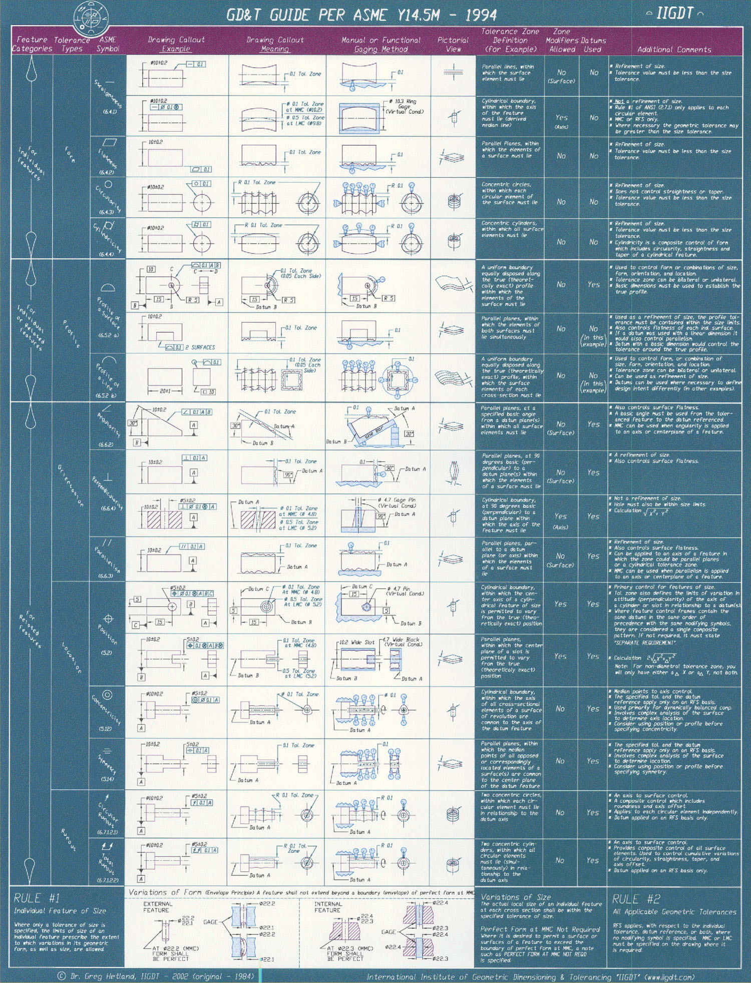
-* annotation primitive. specifically a means to create an object in
- the database that can optionally be associated with another object
- and/or position(s) that a label refers to. there are various styles
- such as a single line from a point to text and two lines (e.g.,
- indicating measurement) to text.
-
- the object should allow for different line styles including having
- no lines. there should also be support for view-fixed or
- view-independent annotation placement (which requires a change to
- plot()'s and possibly prep()'s signature). it would also be useful
- to allow an optional _annotation_ "thickness" so that the
- annotations can represent physical geometry (so they raytrace).
-
- the concept is nearly equivalent to a combined sketch+extrude object
- but with options specific to annotations. the underlying export
- form should be fully generalized as much as possible with a
- higher-level "in" command constraining available options into a
- user-friendly form. a new "annotate" command will similarly be
- needed to support modification of existing annotations (as well as
- creation ala the 'in' command). see the web for tons of examples.
-
- References:
- http://en.wikipedia.org/wiki/Geometric_dimensioning_and_tolerancing
- ASME Y14.5 2009
- http://www.draftingzone.com/shoppingzone/6-1.pdf
-
http://www.wikistep.org/index.php/Recommended_Practices_for_the_Representation_of_GD%26T
-
http://www.wikistep.org/index.php/Recommended_Practices_for_the_Presentation_of_Dimensions,_Dimensional_and_Geometric_Tolerances
-
http://www.wikistep.org/index.php/Associative_Text_in_3D_recommended_practices
-
http://www.wikistep.org/index.php/Model_viewing,_basic_drawing_structure_and_dimensions_recommended_practices
- http://www.iigdt.com/Products/Images/0f390980.jpg
- src/other/openNURBS/opennurbs_annotation*
-
- Types of annotations:
- text: text.
- text --,
- leader: text ---->. \
- . . \ .
. . .
- linear dimension: | | . |
| | |
- . |<-- text -->| --->| text
|<-- -->| |<---- text
- angular dimension: \ text
- \_____.
-
- Annotation placement:
- xyz position: (1.0, 3.5, 2.1)
- named reference(s): hull.r
- above/below/left/right: below
- offset: 33.4
- (e.g., "at 1.0,3.5,2.1" or "below hull.r offset 33.4" or "at
hull.r", etc.)
-
- Text:
- user-defined string: my awesome component -----> .
-
- named/point reference: hull.r1 -----> .
- . .
- automatic dimension (two points): |_______________|
- . . 5.4 mm
- custom dimension label: |<------>|<--.
- \ Length of hull.r1: 5.4mm
-
- (custom label specified via format specifier: "Length of %target:
%size")
-
- Text properties:
- font name
- font size (height)
- font style: bold/italic/regular
- font color
- justification: left, center, right, bottom, middle, top (combinable
options, e.g., "top left")
- placement: default, above, below, inline, interior, exterior
-
- Line properties:
- head style (point o-, arrow_to >-, arrow_from, <-, square #-)
- tail style (point o-, arrow_to >-, arrow_from, <-, square #-)
- line weight (thickness) .___.
target .---- text
- 2d points: text ._____. | \ .
. /
- \ | .---> target |
| /
- .___. -->|
|<---.
- Symbol type:
- degree: (superscript circle)
- radius: ('R', e.g., 'R10.5')
- diameter: (circle with slash, null symbol)
- ... several others
- http://www.tec-ease.com/gdt-terms.php
-
- Annotation properties:
- scale: fixed size or proportional to view
- alignment: to datum (plane or axis) or to view
- draw bounding plane
- draw target axes at uv offset position
- draw feature control frame (characteristic tolerances in symbolic
form: www.draftingzone.com/shoppingzone/6-1.pdf)
- 3d thickness
-
* upgrade source repository back-end to the latest SVN 1.5 so we can
benefit from proper merge tracking.
@@ -445,18 +354,6 @@
* migrate / update screengrab command in libged (libfb/libdm dep)
-* offset surfaces. provide feature edit operation to create a solid
- "level set" style object so you can represent degraded geometry
- states (e.g., damage around a hole in a plate of metal might be
- represented by the toroidal intersection with a cylinder some radius
- larger than the hole, providing a separate region that can have
- different material properties).
-
- geometrically, this is simply a means to separate a given object
- into multiple objects without changing the cumulative volume. a
- linear offset from a given surface or set of surfaces is usually
- desired.
-
* provide libdm mechanism for drawing spline curves (to help visualize
flight paths, show object trajectories, etc.).
@@ -517,18 +414,6 @@
annotations where we can leverage layout components and scalable
vector graphics.
-* Cache objects. These are proper non-geometric geometry database
- objects intended to store binary results that have a dependency on
- other object(s). A named hash (e.g. md5) is recorded for each
- dependent object along with the computed results.
-
- Three potential candidates for leveraging cache objects are 1) prep
- objects containing the final prepped state of a given object
- hierarchy (particularly useful for BoT and BREP geometry), 2)
- raytrace objects containing the intersection results for a given
- view (i.e., a grid of primary rays), and 3) rtgl point samples
- (which is a variant of 2 but potentially view independent).
-
* investigate OpenEXR (BSD licensed HDE image format)
* fix archer/libdm labels/axes to not use pointer printing
@@ -631,24 +516,6 @@
and won't use the currently highlighted solid. undoubtedly related
to libged refactoring. this is related to sf request 2954409.
-* alias objects. this is an object handle in a geometry database that
- refers to another geometry database object. in effect, it
- encapsulates the idea of a symbolic reference for database objects.
-
- alias objects should be very lightweight, corresponding to basically
- a simple named reference to another object. this allows for
- geometry objects to have multiple names, all referencing a given
- primary name. whenever an alias is referenced, it returns the
- object pointed to instead of the alias object itself (this includes
- the rt_db_internal()). this prevents the creation of cyclic
- references.
-
- this directly supports geometry importers that contain object name
- mappings (e.g., part numbers to engineering names) as well as
- simply supporting multiple names per object that one might want to
- persist. there is an issue of whether aliases show as top-level
- objects or even display by default without a listing option.
-
* a "batch" command for libged to apply a given command template to
all lines in a given input text file. could be very similar to exec
but instead of inspecting the current .g, it walks lines in file(s).
@@ -819,54 +686,9 @@
least exist and maybe even try to ensure they will run with null
arguments without crashing.
-* 3D plot objects for v5 geometry files. very closely related to
- other ideas about having 3d wireframe objects, but these would
- probably be non-geometric in nature. basically the plot3 files that
- are stored out to disk being stored as objects in the database with
- support for the overlay command to import, export, display them.
-
- minimally should probably support the basic drafting elements
- (predominantly from collada, dxf, iges, and step specifications):
-
- point := x, y, z
- line := start point, end point
- polyline := various (closed, open, paired, modified, etc.)
- circle := center point, radius
- ellipse := center point, major radius, minor radius
- hyperbola := center point, major radius, minor radius
- parabola := center point, focal length
- arc := center point, radius, start angle, end angle
- spline := degree, control points, knot values
- text := string, insertion point, size, style, alignment
-
* make _plot() callbacks fill in plot objects instead of returning
line segments.
-* image objects (tbd objects) for v5 geometry files
-
-* material objects (non-geometric attribute-only objects) for v5
- geometry files. instead of material attribute value becomes
- material object name. material object encompasses hierarchical
- material traits. some traits potentially of interest:
- - density
- - young modulus
- - yield strength (in different dirs, e.g., rolling & transversal)
- - ultimate tensile strength (also in different dirs)
- - Poisson's ratio
- - cost per ton?
- - ...
-
-* parametric material properties. support the ability to define
- material properties based on parametric values such as distance from
- surface, distance from medial axis, distance from centroid, distance
- from plane, etc. this supports parametric descriptions of materials
- that have highly variable densities (e.g., bone, certain alloys and
- plastics, etc.).
-
-* shader objects (non-geometric attribute-only objects) for v5
- geometry files. allow shader string to refer to said objects for
- shader parameters.
-
* refactor wdb_obj and view_obj in libged. with the de-tcl'ing of the
base libs, it should disappear but shouldn't have wdb_*() funcs in
libged regardless. work in progress.
@@ -1141,8 +963,6 @@
* rtedge shoots twice as many rays as it needs to (shoots the 'below'
ray for each primary, only reusing current scanline cells).
-* support for fillets and chamfers as object/combination operations
-
* make the DSP primitive use less memory when data is coming from
a binunif. allocating 160 times binunif size is a bit extravagant
(which comes from sizeof(struct dsp_bb)).
@@ -1353,6 +1173,191 @@
in BRL-CAD (libraries are BSD licensed: http://ngplant.sourceforge.net)
+NEW OBJECTS
+-----------
+
+* annotation primitive. specifically a means to create an object in
+ the database that can optionally be associated with another object
+ and/or position(s) that a label refers to. there are various styles
+ such as a single line from a point to text and two lines (e.g.,
+ indicating measurement) to text.
+
+ the object should allow for different line styles including having
+ no lines. there should also be support for view-fixed or
+ view-independent annotation placement (which requires a change to
+ plot()'s and possibly prep()'s signature). it would also be useful
+ to allow an optional _annotation_ "thickness" so that the
+ annotations can represent physical geometry (so they raytrace).
+
+ the concept is nearly equivalent to a combined sketch+extrude object
+ but with options specific to annotations. the underlying export
+ form should be fully generalized as much as possible with a
+ higher-level "in" command constraining available options into a
+ user-friendly form. a new "annotate" command will similarly be
+ needed to support modification of existing annotations (as well as
+ creation ala the 'in' command). see the web for tons of examples.
+
+ References:
+ http://en.wikipedia.org/wiki/Geometric_dimensioning_and_tolerancing
+ ASME Y14.5 2009
+ http://www.draftingzone.com/shoppingzone/6-1.pdf
+
http://www.wikistep.org/index.php/Recommended_Practices_for_the_Representation_of_GD%26T
+
http://www.wikistep.org/index.php/Recommended_Practices_for_the_Presentation_of_Dimensions,_Dimensional_and_Geometric_Tolerances
+
http://www.wikistep.org/index.php/Associative_Text_in_3D_recommended_practices
+
http://www.wikistep.org/index.php/Model_viewing,_basic_drawing_structure_and_dimensions_recommended_practices
+ http://www.iigdt.com/Products/Images/0f390980.jpg
+ src/other/openNURBS/opennurbs_annotation*
+
+ Types of annotations:
+ text: text.
+ text --,
+ leader: text ---->. \
+ . . \ .
. . .
+ linear dimension: | | . |
| | |
+ . |<-- text -->| --->| text
|<-- -->| |<---- text
+ angular dimension: \ text
+ \_____.
+
+ Annotation placement:
+ xyz position: (1.0, 3.5, 2.1)
+ named reference(s): hull.r
+ above/below/left/right: below
+ offset: 33.4
+ (e.g., "at 1.0,3.5,2.1" or "below hull.r offset 33.4" or "at
hull.r", etc.)
+
+ Text:
+ user-defined string: my awesome component -----> .
+
+ named/point reference: hull.r1 -----> .
+ . .
+ automatic dimension (two points): |_______________|
+ . . 5.4 mm
+ custom dimension label: |<------>|<--.
+ \ Length of hull.r1: 5.4mm
+
+ (custom label specified via format specifier: "Length of %target:
%size")
+
+ Text properties:
+ font name
+ font size (height)
+ font style: bold/italic/regular
+ font color
+ justification: left, center, right, bottom, middle, top (combinable
options, e.g., "top left")
+ placement: default, above, below, inline, interior, exterior
+
+ Line properties:
+ head style (point o-, arrow_to >-, arrow_from, <-, square #-)
+ tail style (point o-, arrow_to >-, arrow_from, <-, square #-)
+ line weight (thickness) .___.
target .---- text
+ 2d points: text ._____. | \ .
. /
+ \ | .---> target |
| /
+ .___. -->|
|<---.
+ Symbol type:
+ degree: (superscript circle)
+ radius: ('R', e.g., 'R10.5')
+ diameter: (circle with slash, null symbol)
+ ... several others
+ http://www.tec-ease.com/gdt-terms.php
+
+ Annotation properties:
+ scale: fixed size or proportional to view
+ alignment: to datum (plane or axis) or to view
+ draw bounding plane
+ draw target axes at uv offset position
+ draw feature control frame (characteristic tolerances in symbolic
form: www.draftingzone.com/shoppingzone/6-1.pdf)
+ 3d thickness
+
+* offset surfaces. provide feature edit operation to create a solid
+ "level set" style object so you can represent degraded geometry
+ states (e.g., damage around a hole in a plate of metal might be
+ represented by the toroidal intersection with a cylinder some radius
+ larger than the hole, providing a separate region that can have
+ different material properties).
+
+ geometrically, this is simply a means to separate a given object
+ into multiple objects without changing the cumulative volume. a
+ linear offset from a given surface or set of surfaces is usually
+ desired.
+
+* Cache objects. These are proper non-geometric geometry database
+ objects intended to store binary results that have a dependency on
+ other object(s). A named hash (e.g. md5) is recorded for each
+ dependent object along with the computed results.
+
+ Three potential candidates for leveraging cache objects are 1) prep
+ objects containing the final prepped state of a given object
+ hierarchy (particularly useful for BoT and BREP geometry), 2)
+ raytrace objects containing the intersection results for a given
+ view (i.e., a grid of primary rays), and 3) rtgl point samples
+ (which is a variant of 2 but potentially view independent).
+
+* alias objects. this is an object handle in a geometry database that
+ refers to another geometry database object. in effect, it
+ encapsulates the idea of a symbolic reference for database objects.
+
+ alias objects should be very lightweight, corresponding to basically
+ a simple named reference to another object. this allows for
+ geometry objects to have multiple names, all referencing a given
+ primary name. whenever an alias is referenced, it returns the
+ object pointed to instead of the alias object itself (this includes
+ the rt_db_internal()). this prevents the creation of cyclic
+ references.
+
+ this directly supports geometry importers that contain object name
+ mappings (e.g., part numbers to engineering names) as well as
+ simply supporting multiple names per object that one might want to
+ persist. there is an issue of whether aliases show as top-level
+ objects or even display by default without a listing option.
+
+* support for fillets and chamfers as object/combination operations
+
+* image objects (tbd objects) for v5 geometry files
+
+* material objects (non-geometric attribute-only objects) for v5
+ geometry files. instead of material attribute value becomes
+ material object name. material object encompasses hierarchical
+ material traits. some traits potentially of interest:
+ - density
+ - young modulus
+ - yield strength (in different dirs, e.g., rolling & transversal)
+ - ultimate tensile strength (also in different dirs)
+ - Poisson's ratio
+ - cost per ton?
+ - ...
+
+* parametric material properties. support the ability to define
+ material properties based on parametric values such as distance from
+ surface, distance from medial axis, distance from centroid, distance
+ from plane, etc. this supports parametric descriptions of materials
+ that have highly variable densities (e.g., bone, certain alloys and
+ plastics, etc.).
+
+* shader objects (non-geometric attribute-only objects) for v5
+ geometry files. allow shader string to refer to said objects for
+ shader parameters.
+
+* 3D plot objects for v5 geometry files. very closely related to
+ other ideas about having 3d wireframe objects, but these would
+ probably be non-geometric in nature. basically the plot3 files that
+ are stored out to disk being stored as objects in the database with
+ support for the overlay command to import, export, display them.
+
+ minimally should probably support the basic drafting elements
+ (predominantly from collada, dxf, iges, and step specifications):
+
+ point := x, y, z
+ line := start point, end point
+ polyline := various (closed, open, paired, modified, etc.)
+ circle := center point, radius
+ ellipse := center point, major radius, minor radius
+ hyperbola := center point, major radius, minor radius
+ parabola := center point, focal length
+ arc := center point, radius, start angle, end angle
+ spline := degree, control points, knot values
+ text := string, insertion point, size, style, alignment
+
+
+
WINDOWS
-------
@@ -1451,6 +1456,7 @@
as nmg/bot boundary representation meshes. lots of great vehicle
datasets at http://www.ncac.gwu.edu/vml/models.html
+
STEP
----
@@ -1534,7 +1540,7 @@
RTGL
-____
+----
Need before enabling:
This was sent by the SourceForge.net collaborative development platform, the
world's largest Open Source development site.
------------------------------------------------------------------------------
This SF.net email is sponsored by Windows:
Build for Windows Store.
http://p.sf.net/sfu/windows-dev2dev
_______________________________________________
BRL-CAD Source Commits mailing list
[email protected]
https://lists.sourceforge.net/lists/listinfo/brlcad-commits