> On Jul 15, 2017, at 4:00 PM, Mario Meissner <[email protected]> wrote:
>
> Hi Sean.
>
>       • You are right, given the endless possibilities of a function like
> this, it may not be obvious to define the function in the file as I
> mentioned. Some re-considerations would need to be made in order to support
> any number of arguments, any polynomial degree. Who knows, maybe the user
> wants to define the density as a function of the sine or cosine ... (Taylor
> series could be used for these cases... but maybe better figure out the basic
> stuff first).
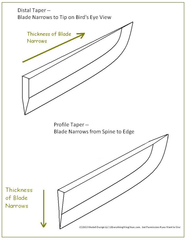
In the general case, we do not necessarily know the “shape" of the geometry,
particularly having an equation for the geometry to substitute in a line
equation like in your case.  For example, the sword blade case might be
constructed as a union of several objects, like if you model this example:
http://www.shopwingchun.com/ewcblog/uploads/blade-tapers.jpg

That would make for a really good simple test case!  Try and model either of
them.

>       • Attached goes an example of how to obtain a function that gives us
> the density a ray sees at is crosses the object. Summing it up, I used the
> two equations that define a line in a 3d space, and made substitution on the
> original density function. The resulting function returns the density of the
> material on each point of the ray. All the extra information gets "wiped off"
> and thus the resulting function is only dependent on a single variable. We
> could even transform this function to make it dependent on the distance to
> the origin of the ray instead of one of the space coordinates, thus
> eliminating "space" completely.

Instead of considering the ray line, whose intersection with geometry is
already covered in a *_shot() function, consider line segments.  Basically,
sets of in/out points (segments) are what you get during geometry evaluation.
Example of two segments (s0 and s1) with two in-points (t0 and t2) and two
out-points (t1 and t3):

     s0             s1
o———————————o    o———————o
t0         t1    t2     t3

With segments, it begs for some function that says — for a given object — what
the density is at point t2, for example, or what the density is from t1 to t2
and t2 to t3.  If calling code knows the density goes from 0.1 at t0 and 0.5 at
t1, then it can integrate to know the average density is 0.3 and represents a
3D mass of XXX*0.3 mm^3.

What’s missing is a density specification that, given t0, t1, or both, can
report the 0.1, 0.5, or 0.3 values.

The simplest starting point that comes to my mind would be simple 3D density
points that are interpolated.  Something like this becomes relevant:
http://docs.qgis.org/2.2/pt_PT/docs/gentle_gis_introduction/spatial_analysis_interpolation.html

>       • For this new example box, I would define the density in
> language-agnostic terms or pseudo-code as the following:
> set box origin density 3;
> 1,0,0 linear density 5;
> 0,1,0 linear density 6;
> 0,0,1 linear density 1.

I think this is on the right track for density specification.  The important
bits are that we define a set of 3D points, a density at each point, and an
interpolation method for in between.  Lets keep it that simple.

> Here I would read it in natural language like:
> At the origin the density of the box is 3. If we go towards 1,0,0 we will
> find that the density changes linearly until it is 5. If we go towards 0,1,0
> it will change linearly until it is 6... etc.

Agreed, this is good!  Only suggestion I think would be to normalize the values
into a 0.0 to 1.0+ range as a density multiplier.  This way, would could apply
the same distribution to different materials.  It will also avoid having
conflicting specifications.  We can still say “this is bone” which has 1.75
g/cm^3 and which would equate to a 1.0 density function value.  What do you
think?


As an aside, here’s a nifty real-world application where we might instruct a 3D
printer to adjust the density of a car’s frame (e.g., the density of some
internal lattice structure) based on how rigid that part of the frame needs to
be:
https://ucarecdn.com/1e2fd4d4-da99-41e0-86ff-3f357dab8181/-/preview/1440x1080/

For that case, you’d pick any one of the densities as your normalized density
(or use the density of the plastic being used), and then have a 3D point cloud
specifying the densities of various zones.

Cheers!
Sean


------------------------------------------------------------------------------
Check out the vibrant tech community on one of the world's most
engaging tech sites, Slashdot.org! http://sdm.link/slashdot
_______________________________________________
BRL-CAD Developer mailing list
[email protected]
https://lists.sourceforge.net/lists/listinfo/brlcad-devel