Well, thanks! But sorry to have doubled the number of things you have
to do now. I hate when that happens... :)
To answer your questions:
The layout of my beamline is documented in MacDowell. et. al. JSR
(2004). I can provide you with a reprint if you don't have access. To
summarize, we have:
source:
superconducting bending magnet.  source size 0.2 x 0.02 x ~2 mm.
Mirror 1:
parabolic collimating mirror: Rh over Pt coated water cooled invar steel
flat mirror bent into a parabola.
motors: 1 stepper: for tilt (we move this about once or twice a year)
monochromator:
Khozu. Two flat crystals. First is water cooled, second is not
cooled. Motors are protected from Compton from crystals by a
water-cooled copper wall.
motors: 5; 1 servo "Theta" (using Heidenhein encoder), 4 steppers to
rotate (Theta2, Chi2) and translate (Y2, Z2) the second crystal. Chi2
is used for steering (many moves/day). Theta2 moves during tune-ups
(1-4 moves/day). Theta and Y2 move with every energy change. Z2 moves
are reserved for large changes in energy. Other than the Heidenhein
encoder for Theta, there is no feedback.
Mirror 2:
toroidal focusing mirror: Rh over Pt coated uncooled silicon mirror. 2:1
demagnification to eliminate spherical aberrations.
motors: 3 steppers; 2 to bend (moved once or twice a year) and 1 to tilt
(moved all the time).
Feedback:
Beam is actively steered vertically (M2 Tilt) and horizontally (Chi2)
using a video camera pointed at a phosphor on the back of the fast
shutter as a beam position monitor.
Apertures:
the superbend has an exit aperture
the M1 mirror has an entrance aperture that defines the input acceptance
of the beamline
the mono has an entrance aperture that serves as a guide for tilting M1
the M2 mirror has adjustable entrance slits for defining the beam
convergence angle on the sample
there is a pinhole (round 100 um) just before the sample position

That is pretty much it.

WRT the second crystal:
Motion of the second crystal CAN cause small changes in energy. This is
because the Bragg reflection from the first crystal has some width to
it, and also has long "tails". Rotating the second crystal (what we
call Theta2) will cause it's rocking curve (Si111) to select from these
available energies. However, the first thing you will notice from the
second crystal rotating is a VERY significant drop in flux, combined
with beam drift. Just as though you had intentionally moved the crystal
with a motor. Since you didn't mention a drop in flux, I think you can
eliminate your mono "falling off the rocking curve" as the source of
your energy drift. If you are still not sure, try intentionally tilting
your second crystal to see if it changes your photon energy.
The only way to get an energy change without a loss of flux is for the
two crystals to remain parallel. In other words, the whole
monochromator must tilt relative to the incoming beam. Note that this
will not change the angle of the exiting beam relative to the incident beam.
I am assuming you are using fluorescence scans to assay your photon
energy, but you can also see the energy dispersion in the tails of your
beam at the sample position. Take out any pinholes or sample slits you
might have and put a phosphor screen in the beam (at a relatively steep
angle to spread out the vertical structure of the beam spot). Then put
in a selenium absorber foil and dial up the selenium edge. As you pass
through the Se edge, you will not see the intensity of the beam drop all
at once, but rather a dark "curtain" will sweep through the beam
profile. This is because different parts of the beam actually have
different photon energies! Especially any long scatter "tails". The
reason why I mention this is because I think you could use a method of
checking your photon energy that does not involve moving motors.
The best advice I can give anyone who is trying to solve any kind of
drift problem is: DON'T TOUCH ANYTHING! It is very tempting to keep
trying to fiddle with one thing after another, but if your drift is on a
timescale of 1 day, then you can only do one controlled experiment each
day. This is because you are effectively dealing with a different
beamline each passing hour, and you are also changing things every time
you fiddle. There is no way to know if the results of your changes will
take seconds, minutes, or days to have an effect. Heat takes time to
conduct, and once you have "exercised" a motor, it can take up to an
hour or more for the heat you created to find its way into something
that will move the beam when it expands, and even longer for the heat to
dissipate completely. For my "Z2" motor heat problem, it took ~8 hours
for the beamline to "settle down" after that motor was "exercised".
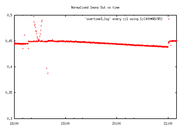
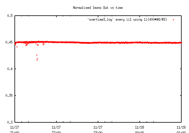
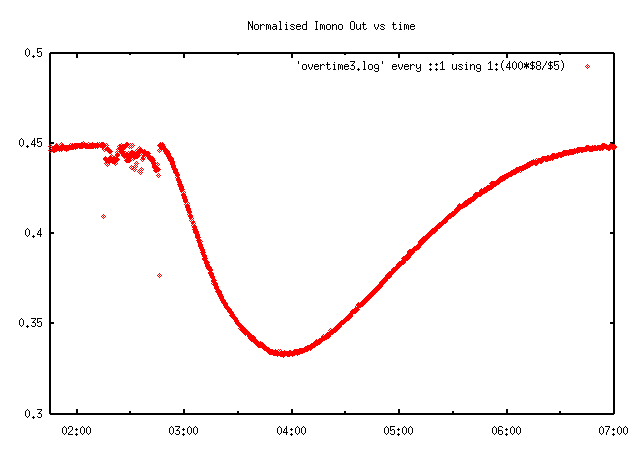
For sake of example, I have the graph from my mono motor heating
diagnostics here:
http://bl831.als.lbl.gov/~jamesh/old_pickup/Theta.bmp
http://bl831.als.lbl.gov/~jamesh/old_pickup/Y2.bmp
http://bl831.als.lbl.gov/~jamesh/old_pickup/Z2.bmp
The x axis is time and the y axis is the current from a 1 um aluminum
foil at the exit flange of the monochromator, normalized to the ring
current. "Theta" is the Bragg angle of the monochromator, and Y2 and Z2
are the two translation stages for the second crystal. Prior to each of
these graphs, I let the beamline sit for at least 8 hours. This was the
amount of time it took for the intensities and beam positions to "level
off". Then I moved one motor (the wiggles on the left side of the
graph) back and forth between two positions to "exercise" it, and then
drove it back to the starting position, turned it off again, and then
went to bed. Note that although Z2 had a pronounced and long-term
effect, it took ~30 minutes before the effect showed up!
I highly recommend that you try the experiment of turning as many
things off as you can, and then let the beamline sit for at least one
day. You may want to post signs telling people to keep away from it.
If the beam drifts to the point where you can't see it anymore, then you
will have to tune it up again, but then you must leave the beamline to
calm down for another full day. This takes a great deal of discipline
(try not to think about all the "wasted photons"), but it is the only
way to prepare an "equilibrated" beamline for doing a controlled
experiment, such as moving a motor.
It is also possible that your beamline will never "calm down" or "level
off". If you still see this "circadian drift" with all the motors
turned off and you have not moved or fiddled with anything for a day or
two, then you have just eliminated a tremendous number of variables.
The most important of which is you. That is, you didn't touch anything,
so it's not your fault. Must be someone else's fault. Sounds childish,
but it works. If you can demonstrate that your problems are not due to
human activity in your area, then it does tend to convince the storage
ring folks that they might have a problem on their end. Nothing settles
a debate quite like good data.
It would be nice if you could demonstrate seasonal effects as well, but
I see on Google Earth that you are about as close to the equator as
Hawaii. So, probably no luck there?
All in all, it sounds to me like your storage ring support struts are
getting longer with the heat of the day. If you have a downstream
aperture (such as the entrance slit of the mono) that is not getting
quite as tall (or perhaps taller), then you have introduced an angle
shift. On a low(ish) emittance source you will not see much of a flux
drop because your aperture is still well within the fan of radiaiton
emitted by the source, but the change in angle of the light coming into
the mono will change your photon energy. Note that tilting the wiggler
will not change the angle of the photon beam. The light comes from the
electrons, not the magnets. But changing the height of the electron
beam relative to an aperture will change the angle.
HTH

-James Holton
MAD Scientist

Lucas Sanfelici wrote:
Hey James!

Man, you did really organize my thoughts!

Weeks ago I did the calculations you mentioned but without paying
attention to certain points. After I read your message the # of tests I
intent to do almost double!

With regards to mono heating I'm particularly worried about the 2nd
crystal, which has no shielding, no cooling and no feedback! However,
this will be probably a minor effect since the features of the energy
and position drifts is much correlated to room temperature! In addition,
I heard sometime from the machine guys the temperature homogeneity
inside the tunnel is not good - several degrees instead of .xºC! By the
end of last year we measured temperature along 10 points of the beamline
and we did not noticed any appreciable temperature difference (see
attached figure) upon the supports of a same optical element, at least
not that could lead to something near of 40urad(3eV @ 12657eV).

You definitely took my attention when you mentioned the motors
influence. We have a temperature sensor only for the goniometer motor
(Huber) and it says the motor is kept around 40ºC when steady. In order
to minimize gradients inside the mono we increased the temperature of
the 1st crystal cooling water to the same 40ºC, but it seems not to
result in any change!

Do you have to say about heating on the 2nd crystal? Is your 2nd crystal
cooled too? What kind of control system did you implement?

It seems the best way to track is really attempt to angles coupled by
temperature gradients!... I enjoyed the laser pointer idea. In the case
I don't used it right now, I'm sure it'll be useful in my life someday!
:)

Thanks one more time for the valuable help,

Lucas.

-----Mensagem original-----
De: CCP4 bulletin board [mailto:[EMAIL PROTECTED] Em nome de James
Holton
Enviada em: sábado, 26 de julho de 2008 17:38
Para: [email protected]
Assunto: Re: [ccp4bb] Beamline Stability Issues
As I recall, your setup down there is similar to mine (ALS 8.3.1), so
perhaps I can be of some assistance.
There are only two things that can cause changes in energy: d and
theta. This is because lambda=2*d*sin(theta). If the change is
entirely due to thermal expansion of the mono crystal, then the
fractional change in wavelength or energy (3 eV is 0.03% of 12657 eV)
must equal the fractional change in cell edge. 0.03% may not sound like
much, but the thermal coefficient of linear expansion for silicon is
only 2.6e-6 / K, so this change represents a shift in crystal
temperature of 121 C. I doubt your cooling water is getting that hot.
This leaves theta (or rather 2*theta) as the culprit, and for this
change in energy you are looking for a tilt of 0.005 degrees or 0.1
millirads. This is a change of 100 microns over 1 meter, which
represents a temperature difference of 8 C if you have two steel support
legs (expansion coefficient: 12e-6 /K) 1 meter tall and 1 meter apart.
This is not too hard to imagine. If your supports are made of aluminum
(TCE = 23.5e-6 /K), then a 3 C change in one leg of a square will make a
0.1 mrad tilt. Good news is, this change in tilt must be happening
either inside (or underneath) the mono or somewhere upbeam from it.
Focus your attention there.
As Liz pointed out, temperature fluctuations can always be a headache,
and it is important to remember that your x-ray beam is not the only
source of heat you need to think about. Motors generate heat (such as
the ones in your mono). I too saw a lot of drift in the second crystal
of my Khozu monochromator when we first got it, but this turned out to
be due to heating of the "Z2" motor. This motor only moves when you
change energy and at first I thought it was just bad luck that we were
seeing big drift during every MAD data set. Nowadays we only move this
motor if the beam is in danger of walking off the edge of the crystal
(~2 keV moves), and the mono is remarkably stable now.
Another things you might not expect is computers. I recently narrowed
down a large (1 mm) beam drift problem on ALS 8.3.1 to tomography
reconstruction jobs at 8.3.2. They had bought a new computer and
happened to accidentally point its exhaust fans at the downbeam support
leg of my M2 mirror tank. The extra CPU heat from the tomography jobs
was enough to heat the support by ~10 C, which moves the beam at the
sample position (10 meters away) by 1 mm. Took me a while to figure
that one out.
Since your fluctuations are not correlated to ring current, I am
willing to bet that heat from the x-ray beam is not your problem. More
likely a different source of radiation (with lower photon energy, but
higher total power) is to blame. Your energy drifts seem to start at
sunrise and then turn around at sunset? Although it is tempting to just
tell your facility that they need to buy a better air conditioner, a
more cost-effective solution will probably be to figure out exactly what
is moving and do something to fix it. It is still possible that you are
doing something every morning that starts the drift (such as moving a
lot of motors to optimize the beam).
Measuring the temperature of the optics support legs is always useful,
but you can also get a lot of mileage of of a laser pointer, a mirror, a
piece of paper and a pen. Rig the laser pointer to a remote power
source (you don't want to have to touch it to turn it on), attach it to
something "stable" (like the shield wall) and bounce the laser off a
mirror mounted on your mono tank, and back to a piece of paper near the
laser pointer. Use the pen to mark where the beam falls at different
points of the day. You can catch very small angles this way, and you
might get lucky.
Good luck,

-James Holton
MAD Scientist


Lucas Sanfelici wrote:
Hello all!

Does someone have experience in minimize energy instabilities in
beamlines?
MX2, our new beamline devoted to MX experiments, are facing problems
with energy drifts. As far as we could notice, theses drifts are
results
of the contribution from several sources - possibly electron beam
movements, heating of optical elements, etc...

LNLS is a 2nd generation machine with 4 straight sections available
for
insertion devices. MX2 is a 2T wiggler-based beamline and produces a
peak flux of 10^11 photons/s.

What I'd like to know, before start performing calculations, how far
should I expect the heating of a non-cooled 2nd crystal affects
energy?
Does someone know cases of a few eVs drifts?

Thanks in advance and regards,

Lucas Sanfelici
Physicist
Brazilian Synchrotron Ligth Source- LNLS (www.lnls.br)
Diagnostics Group
PO Box 6192 Postal Code 13083-970
Campinas-SP Brazil
Phone: +55-19-3512-1153/1152  Fax: +55-19-3512-1006
E-mail: [EMAIL PROTECTED]