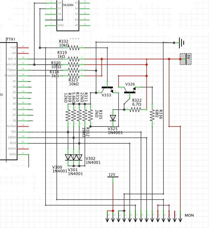
>>> http://www.binarydinosaurs.co.uk/STCExecutelSyncCircuit.jpg
>> I don't believe it's correct as drawn.  For one thing you have V333,
>> an NPN transistor, with the collector grounded (and no -ve supplies
>> on the circuit.
Bipolar transistors are to some extent symmetric under interchange of
collector and emitter.  Simplified pictures showing a bar of
semiconductor with the ends being emitter and collector and a thin base
layer in the middle are, well, simplified, but there is _some_ truth
lurking in them.

However, the only reason I could see that being done deliberately is if
the circuit is analog and the transistor's behaviour is relevantly
different from the normal way around.  This circuit doesn't look like
that to me.  Redrawing it a bit less confusingly with V333 E/C swapped
makes it look as though V333 and V326 are being used in their switching
regions, not their linear regions.

The lack of negative supplies is hardly conclusivein itself; negative
voltages could be developed in any of many ways.  However, V325, R322,
and V326 would make it difficult for the R335/V325/V333 junction point
to get too far below 5V (admittedly this is much less true if R322's
value is actually significantly higher).

I also question the way R311/R310/R309 are all different.  I would
expect the red, green, and blue circuits to be electrically more or
less identical, and different pulldown values does not fit with that.

>> For another, R322 is ridiculously low.

Indeed.

I don't know how much you know about electronics at the relevant level,
so it's possible what I'm about to say is unnecessary or has already
been considered.

Did these resistor values come from reading bands, or measuring
in-circuit, or what?  Note that R322 is in parallel with the C-B diode
of V326; a simple ohmmeter put across it may end up measuring the diode
drop instead.  (To test this theory, switch ranges.  A diode drop will
usually give you approximately the same digits in each range - eg, 6.7
ohms on the 0-10 range, 67 ohms on the 0-100 one, 670 ohms for the 0-1K
range, etc.  Also, swapping the probe leads will give a different
reading if that's what's behind this.)

>> And I would expect the anodes of the 3 diodes on the RGB outputs to
>> go somewhere other than a resistor to ground.

At least with R312 as high as 10K.  If it were much lower, the diodes
could be clipping diodes; a diode drop is not too far from about the
right swing for a video signal.

/~\ The ASCII                             Mouse
\ / Ribbon Campaign
 X  Against HTML                [email protected]
/ \ Email!           7D C8 61 52 5D E7 2D 39  4E F1 31 3E E8 B3 27 4B