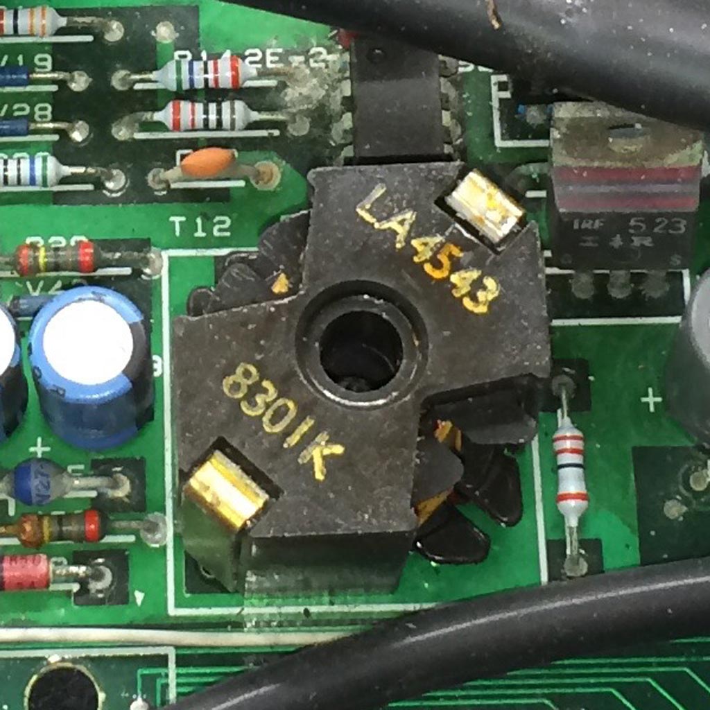
On Sat, Jan 21, 2017 at 11:33 PM, Adrian Graham
<[email protected]> wrote:
> On 21/01/2017 21:59, "Tony Duell" <[email protected]> wrote:
>
>> On Sat, Jan 21, 2017 at 8:43 PM, Adrian Graham
>> <[email protected]> wrote:
>>> Hi folks,
>>>
>>> Does anyone know what this is? It's obviously a transformer coil(s) but
>>> image search and googling those markings produces nothing:
>>>
>>> http://www.binarydinosaurs.co.uk/la4543.jpg
>>
>> I think the LA number is the number for the ferrite 'pot core' not the
>> complete transformer.
>>
>> It looks to be part of a switching regulator circuit. Possibly to generate
>> other voltages from the 5V line. Can you post a picture of more of the PCB
>> around it.
>
> Its second output goes via an IN4148 to the -24V regulator:
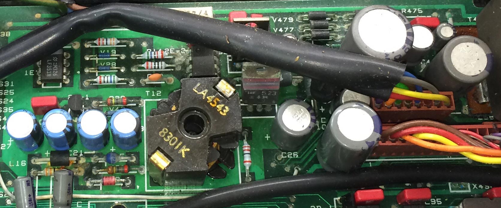
What do you mean by 'second output'? How many pins are used on this
'transformer'? If only 2 it is just a simple inductor, again possibly part of
a swtiching regulator.

>
> http://www.binarydinosaurs.co.uk/STCExecutelPowerRegulation.jpg
>
> The top black wire is from the PSU and goes left-right (in pairs) GND, +5,
> +12, -12. I'd do an underside pic too but the board's covered in analyser
> wires at the mo.
>
> The -24V regulator can be seen just above the 4 blue caps, The regulator
> that can be seen under the black wire is a 7812. The LF351N has -12V present
> at its bias outputs, the opamp to its right has no markings helpfully.

What about that IRF523? That is a power MOSFET transistor and might well
be the chopper in the switching regulator circuit.

Why do you assume the other 8 pin IC is an op-amp?

-tony