again, I don't know the circuit, but I have personally witnessed this behavior
on my PDP-8/e where a 7474 flip flop chip was bad. The input looked great and
the output was "half baked"
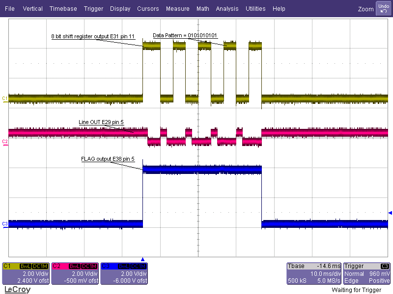
I'll bet that flop was a Fairchild.

Dwight


________________________________
From: cctalk <[email protected]> on behalf of W2HX via cctalk
<[email protected]>
Sent: Wednesday, March 29, 2017 6:48:09 PM
To: General Discussion: On-Topic and Off-Topic Posts
Subject: RE: Cross-talk square-wave?

I am still not convinced it is coupling at all. You would expect the affected
line to show a signal like dV/dt , no? I just don't think you can get square
waves from square waves. That's not to say the input of some logic somewhere
isn't getting triggered by unintended coupling and then getting "squared up" in
some gate to produce the square we see.

Oh, and 270K surely is a transmission line load if the source has a
characteristic impedance of 270K. Granted, that seems unusual and I don't know
what the circuit looks like, but yes, most probably it is not a matched load.
Having said that, given such a probable mismatch, then it is even harder to
believe one could successfully couple a square wave onto such a transmission
line unless the signal is actually being asserted on the line at a low
impedance (ie the intentional output of a gate somewhere).

Looking at this picture
http://pdp10.froghouse.org/qsic/pic_24_1.gif

this shows exactly what I would expect to see with cross talk the little
glitches on the CS line that correspond to edges on the clock signal. Classic
dV/dt. scenario.

Looking at this one
http://pdp10.froghouse.org/qsic/pic_24_2.gif

again, I don't know the circuit, but I have personally witnessed this behavior
on my PDP-8/e where a 7474 flip flop chip was bad. The input looked great and
the output was "half baked"
Here is a screenshot of what I was seeing (look for "Line OUT E29 pin5" on the
scope screenshot...)
http://w2hx.com/x/VintageComp/PDP-8e/M8650/LecroyScreen14.png
(post on that subject is here:
http://www.vcfed.org/forum/showthread.php?55171-PDP-8-e-Project/page6 )

Anyhow, I dunno. My jury is still out on this one.

Eugene


-----Original Message-----
From: cctalk [mailto:[email protected]] On Behalf Of dwight via
cctalk
Sent: Wednesday, March 29, 2017 8:33 PM
To: Al Kossow; General Discussion: On-Topic and Off-Topic Posts
Subject: Re: Cross-talk square-wave?

270K is not a transmission line load.

As I recall ribbon cable is around 100-150 ohms

impedance some place.

The signal does look nice and square.

I doubt is is inductive coupling, with that high a

load, I'd say it was capacitive.

inductive coupling requires current flowing.

Dwight


________________________________
From: cctalk <[email protected]> on behalf of Al Kossow via cctalk
<[email protected]>
Sent: Wednesday, March 29, 2017 2:35:54 PM
To: [email protected]
Subject: Re: Cross-talk square-wave?


On 3/29/17 2:14 PM, David Bridgham via cctalk wrote:
> And I think this picture is the smoking gun.
>
> http://pdp10.froghouse.org/qsic/pic_24_2.gif
>
> Again, the bottom trace is the CS signal in question and the upper
> trace is now one of the QBUS DAL lines (after the bus transceiver and
> level
> converter) that's running across the ribbon cable near the CS signal.
> It does appear that induction can make a fairly clean square wave.
>
>

simple thing to try is split the ribbon cable between the two signals