Since you know the pinout of the SIO chip, you might first look to see if where
the rx and tx pins go. This may require some hunting with an ohm meter. I'd
suspect they go to a RS232 level shifter.
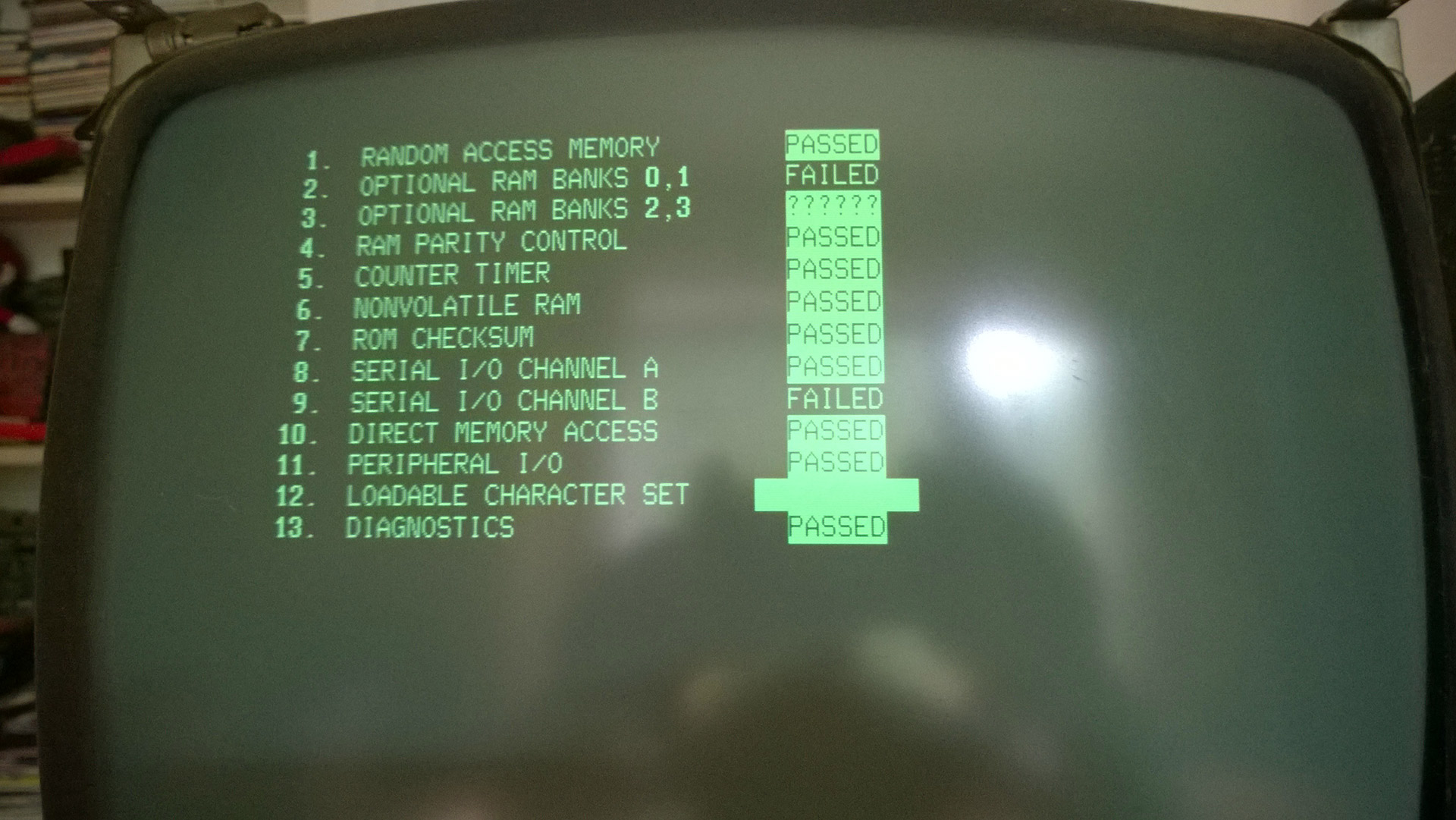
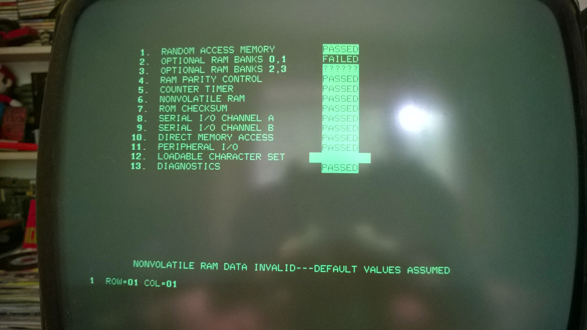
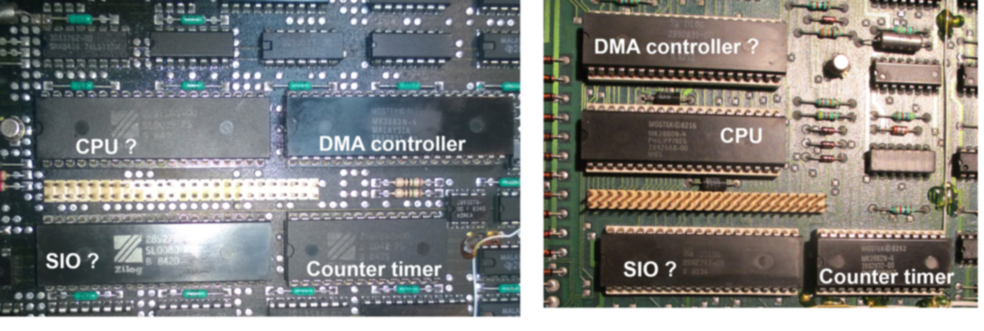
You may also have to write some code to run the serial chip and any possible
external loopback. As I recall these chips may have an internal loopback.

If you have a working logic analyzer, you can trigger on the select pin to the
SIO and look to see what address the SIO is located at. That will allow you to
create some debug code.

I'm not saying this is easy. Still, this is the way I'd attack the problem as a
start.

You have to realize, there is not much more we can do for you.

Creating a ROM with a diagnostic looping program is about the only practical
way to deal with a machine with no documentation.

I fixed an old mini once without schematics but it was all DTL and TTL and
there were signal names at the card edges.

You have a Z80 computer. If you can program EPROMs you have a chance, otherwise
it is unlikely that your current easter egg hunting method is likely to be very
fruitful. You have already gone through most all of the likely failure items.
From here you will likely have to begin to troubleshoot.

Dwight


________________________________
From: cctalk <[email protected]> on behalf of Dominique Carlier via
cctalk <[email protected]>
Sent: Tuesday, October 17, 2017 1:59:47 PM
To: Chuck Guzis; General Discussion: On-Topic and Off-Topic Posts
Subject: Re: The SPERRY UNIVAC UTS 40 system + 8406 double-sided diskette
subsystem : Restoration

Thanks for your response Chuck,

As described in the topic, just after the Power On, the machine runs a
self-test which is called "POC TEST" on the UTS range of Sperry Univac.
During this test, the machine checks the status of the RAM, the ROMs,
the Counter Timer, and the various communication interfaces.
Everything is OK except the ninth line which says: "SERIAL I / O CHANNEL
B: FAILED"

(ignore the FAILED next to "OPTIONAL RAM BANK 0,1", the machine can
start without this board)
http://www.zeltrax.com/classiccmp_forum/uts40_screen03.jpg

This channel B error completely freezes the machine, it does not load
the default settings, I no longer have access to the setup page, in this
situation the keyboard remains without effects.

When the POC test is successful, it loads the default settings in non
volatile RAM:
http://www.zeltrax.com/classiccmp_forum/uts40_screen01.jpg

And I can access the setup page:
http://www.zeltrax.com/classiccmp_forum/uts40_screen02.jpg

The few times I was able to go into the setup page (CHANNEL B: PASSED),
I rushed to try to encode (with the dead keyboard) the data to declare
the subsystem and finally return to the CP/M mode. And I had twice the
case where without warning hop! Blank screen, automatic reset, self-test
(POC) -> SERIAL I / O CHANNEL B: FAILED (again).
Maybe we have there some interesting information about the problem, the
intermittent nature of this failure, could this give information about
the type of component in fault?

But note that since weeks now the problem has become permanent, I have
never been able to return to this famous setup page and the "serial I/O
channel B" is now always marked as 'FAILED'.

So I have no way to try anything using the terminal at this point.

It is possible that the breakdown is in fact very simple (dry solder dry
or attacked solder by the acid of the battery), but I would like to
avoiding to rework all the solders, and maybe to finally find that the
problem was at the level of an IC, I would try to locate the components
linked to this problem. I look at the SIO, try to discover what is after
just after, see how I can eventually act on the pin 30 (W/RDYB) of that IC :
http://www.sbprojects.net/projects/izabella/assets/images/sio1.jpg


And try to understand why this SIO no longer considers the channel B as
'READY'
This kind of things ...
There are probably programmable loop-back circuitry used by the POC test
program (in the ROM of the program cartridge).To ignore the negative
diagnostic I would like to induce to the self-test program that the
channel B is OK, what should I inject to the SIO (perhaps on this pin
30) to force a positive diagnosis?
It would be interesting, just to see if in that way I can take control
again on the machine, and check that the rest is working.

And yes, the SIO is working (as the CPU, the counter timer and the DMA
controller) because I replaced these IC by another ones with the same
faulty result.
http://www.zeltrax.com/classiccmp_forum/sio_issue_01.jpg

Thanks for your help ;-)

Dominique


On 17/10/2017 20:22, Chuck Guzis via cctalk wrote:
> On 10/17/2017 10:50 AM, Dominique Carlier via cctalk wrote:
>> Hi Chuck,
>>
>> Yes I understand well. But the fact that the machines Z80 based were all
>> equipped with this famous serial I/O channel A and B, I therefore
>> thought that the principle of verification of these channels would
>> probably be the same on this type of architecture (Z80+PIO+CTC+SIO).
>> Therefore, there should be probably more people able to give me some
>> useful information.
> Perhaps, but we don't know exactly what surrounds the Z80 SIO, or
> exactly what the diagnostic is complaining about.   Does your SIO have
> anything other than line drivers or receivers on its external interface?
>   Some systems have programmable loop-back circuitry to enable the
> terminal to function to talk to itself and verify functionality.
>
> If you ignore the diagnostic message and feed the terminal some serial
> data, do the inputs on the SIO wiggle appropriately in response?  In
> other words, is the data getting from the connector to the SIO chip?
>
> Troubleshooting is slow, methodical work.
>
> The SIO/DART chip itself is very simple--and most likely not the cause
> of the diagnostic failure.  But writing your own diagnostic software can
> verify that.
>
> At least that's what I think from a few thousand km away.
>
> --Chuck
>
>