Here's my conclusion to the H960 stabiliser feet thread from a while ago where
I was after measurements of
the originals. And thanks for all the help from cctalk (especially Noel) who
supplied dimensions and photos.
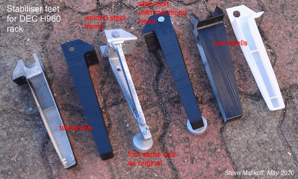
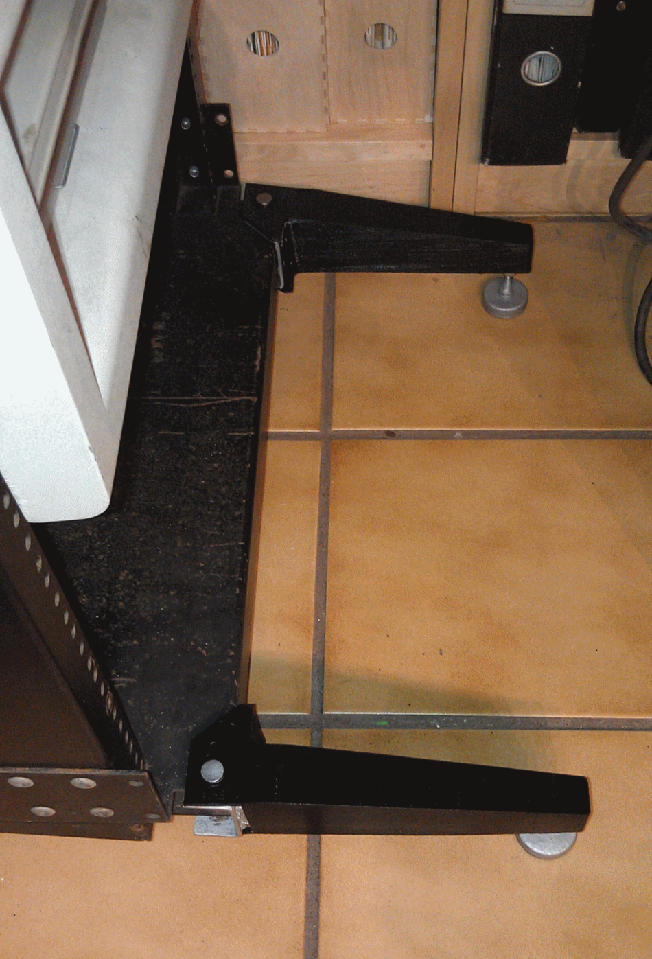
I finished these last year but moved on to other projects and hadn't returned
to the list to discuss them,
so I am doing that now. I made a pair each for my two H960's.

The feet consist of welded steel load-bearing frames with a C-profile that fits
snugly onto the H960
base, a lower leg from a shelf bracket and a support strut. The leg is located
by a steel bolt. The
bolt has the head machined to a disc, I was going to turn the taper and machine
the slot but I lost
the photo of the original bolt that a listmember had posted so I left them at
that. They could do with
nickel electroplating sometime. The frame is super strong, although I have not
physically loaded them
to any great extent.

The outer end has a threaded adjustable pad the same size (AFAIK) as the
originals, which are still
available. I found some correct size el-cheapo ones at the hardware store that
did the job just fine.
The frame is threaded for the pad post and a nut on the pad then locks the pad
from turning.

The outside aesthetics are taken care of with a 3D printed hollow shell
modelled from the measurements
of the original casting. It slides onto the leg and is secured by the bolt. The
shell CAD model still
needs some work to get the fit and front holes right, and a few other things
but overall they look
fine and obey the 6 foot rule. A few coats of satin black enamel helps hide the
print layering a bit.

Photo showing the frame (spray finished in silver epoxy primer, what I had at
hand), the other frame
inside a shell, and some of the test shells:
http://www.surfacezero.com/g503/data/500/Stabiliser_feet_01.png

As attached to one of the H960s. (I have yet to do the kick panel, may laser
cut that sometime):
http://www.surfacezero.com/g503/data/500/Stabiliser_feet_02.png

Steve.