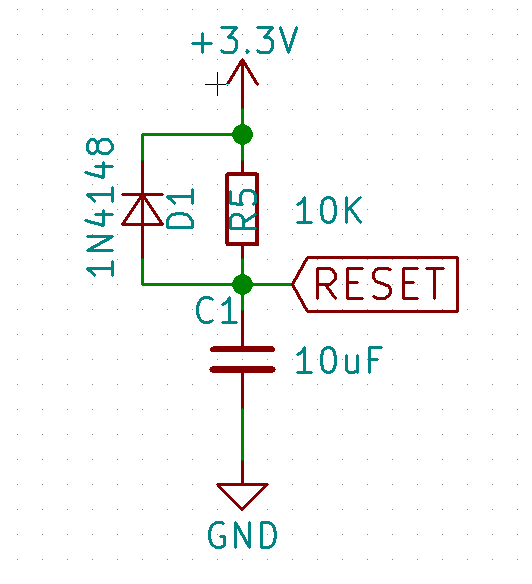
Hi Arsenijs,

> The simplest (and workable) solution contains three components:
> https://cdn.hackaday.io/images//835881528719783422.png
How is it any better than the 74AXP1T34 solution which I outlined in
detail in my original post?  My proposed solution adds just *one*
component to the board, which is available in 1.0x1.0 mm, 1.0x0.9 mm
and 0.8x0.8 mm QFN packages, and costs about 70 cents from Digi-Key.

I would not want to use your proposed solution in a board design that
costs ~4 kUSD fully at risk to produce.  The reset generated by your
circuit is not coordinated with any of the system's existing
on/off/boot/reset sequence control signals; one might be able to tune
the R and C values to get the timing approximately right, but the slow
rise of the reset line would still be bad.  OTOH, my proposed solution
takes an already existing and ideally suited reset signal and simply
level-converts it from 1.5 V to the needed 2.8 V.

> If your chip(s) don't have
> hysteresis RST inputs, you might want to put a single-gate non-inverting
> buffer

In my proposed solution I am already using a single-gate non-inverting
buffer, it just also has separate Vcci for input and Vcco for output
to support logic voltage level translation.

> or some other gate if you want to use RST signal from other
> sources at the same time.

That's what I am doing, except that there is no need for your proposed
RC circuit at all because there already exists a perfectly suitable
reset signal, just at a wrong voltage logic level.

M~
_______________________________________________
Community mailing list
Community@freecalypso.org
https://www.freecalypso.org/mailman/listinfo/community