  Igor,

Given the high RF voltage at the PA on 3.5 MHz, you may have an open Low
Pass Filter - check for continuity on the 2 band board from P3 pin 1 to
P3 pin 8 for both bands.  If one or both are open, you have a poorly
tinned toroid lead.
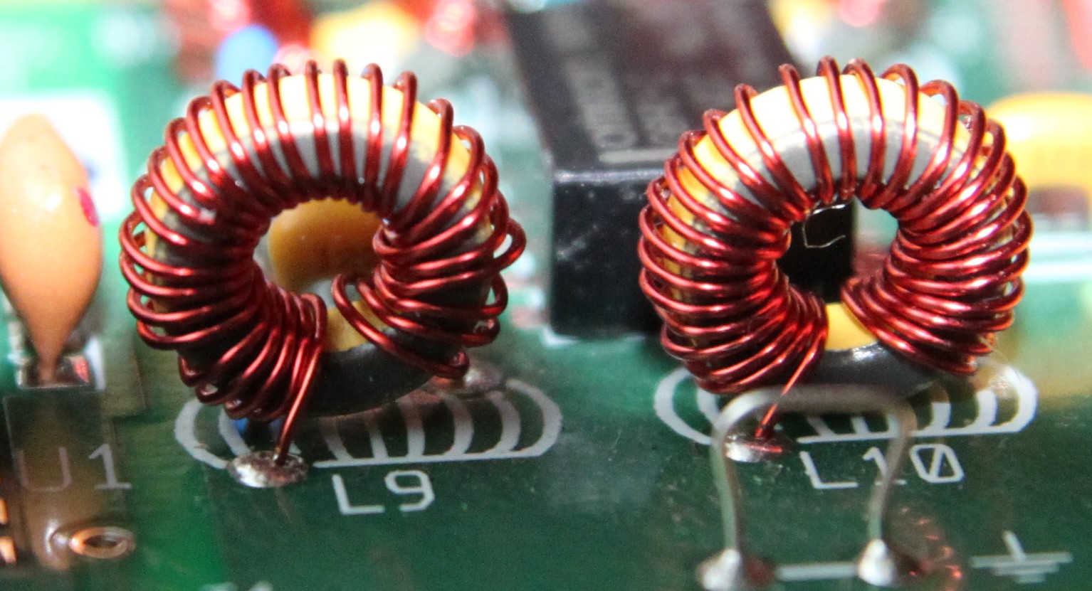
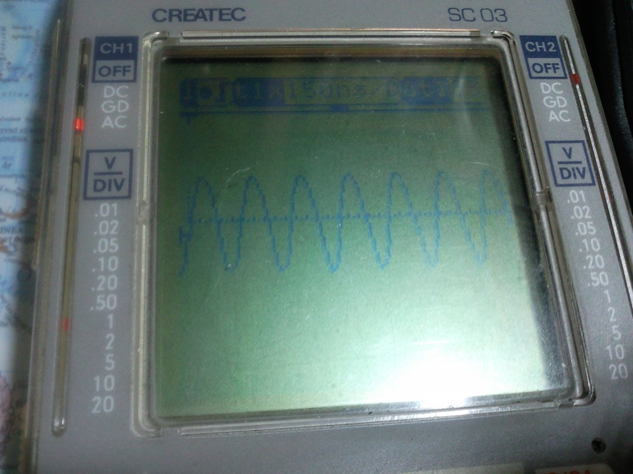
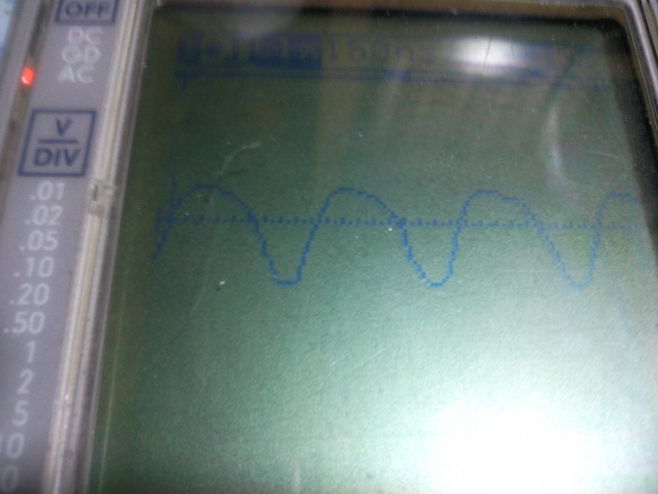
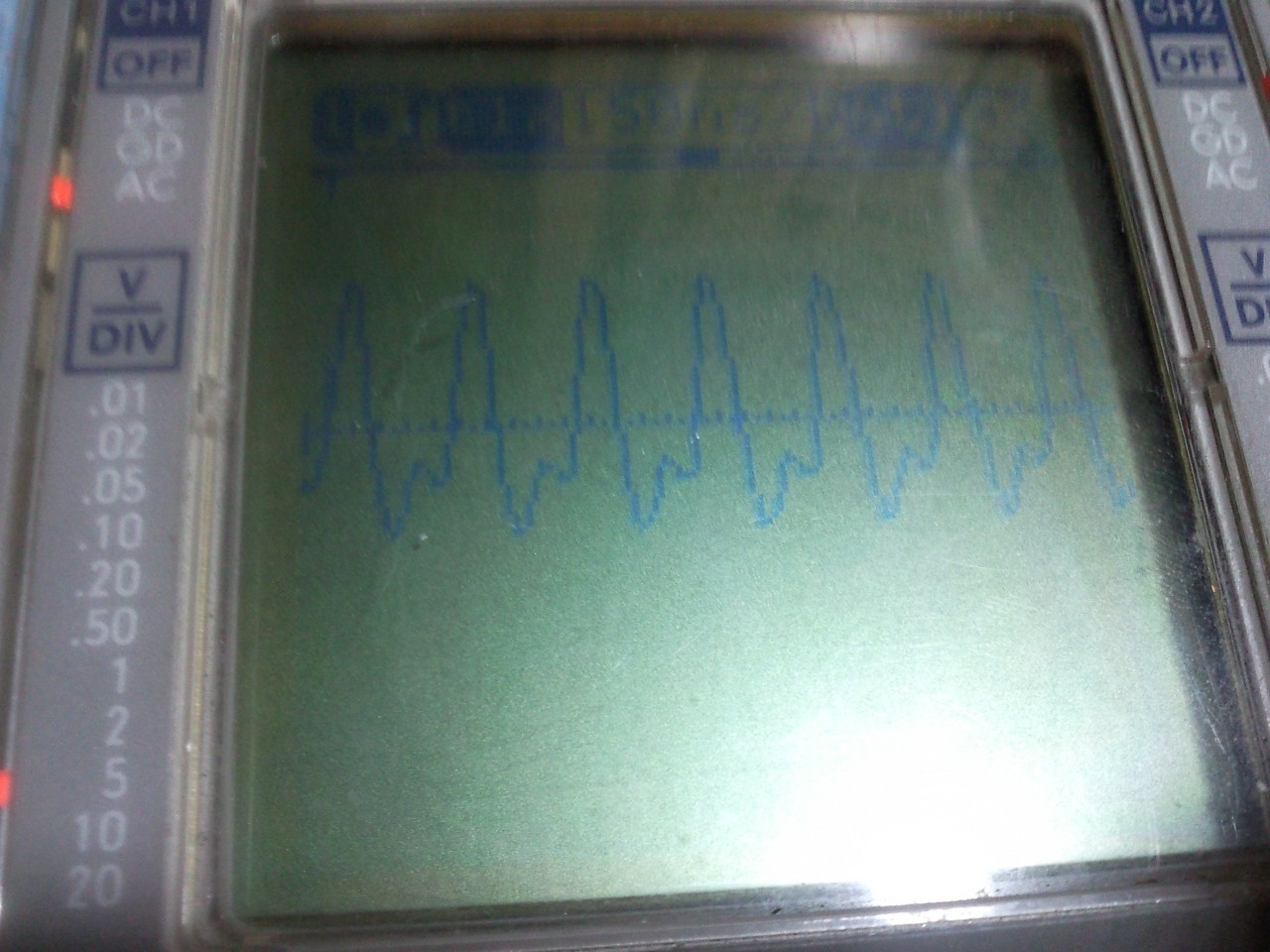
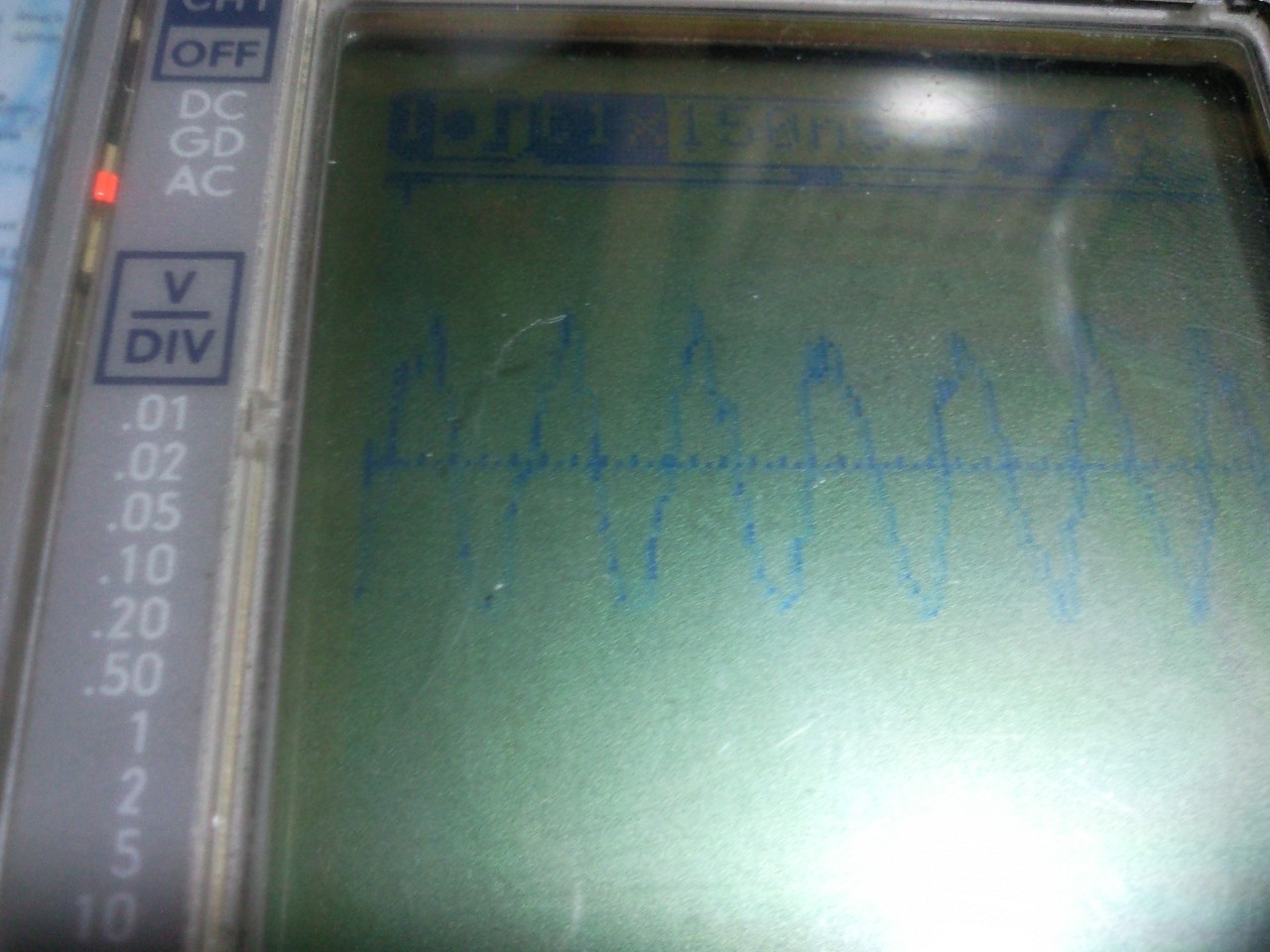
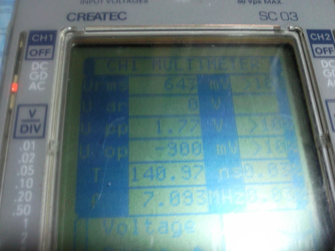
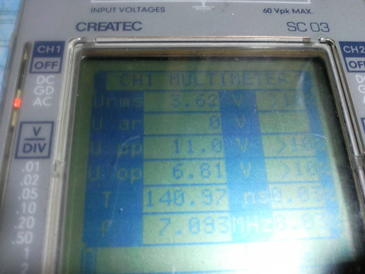
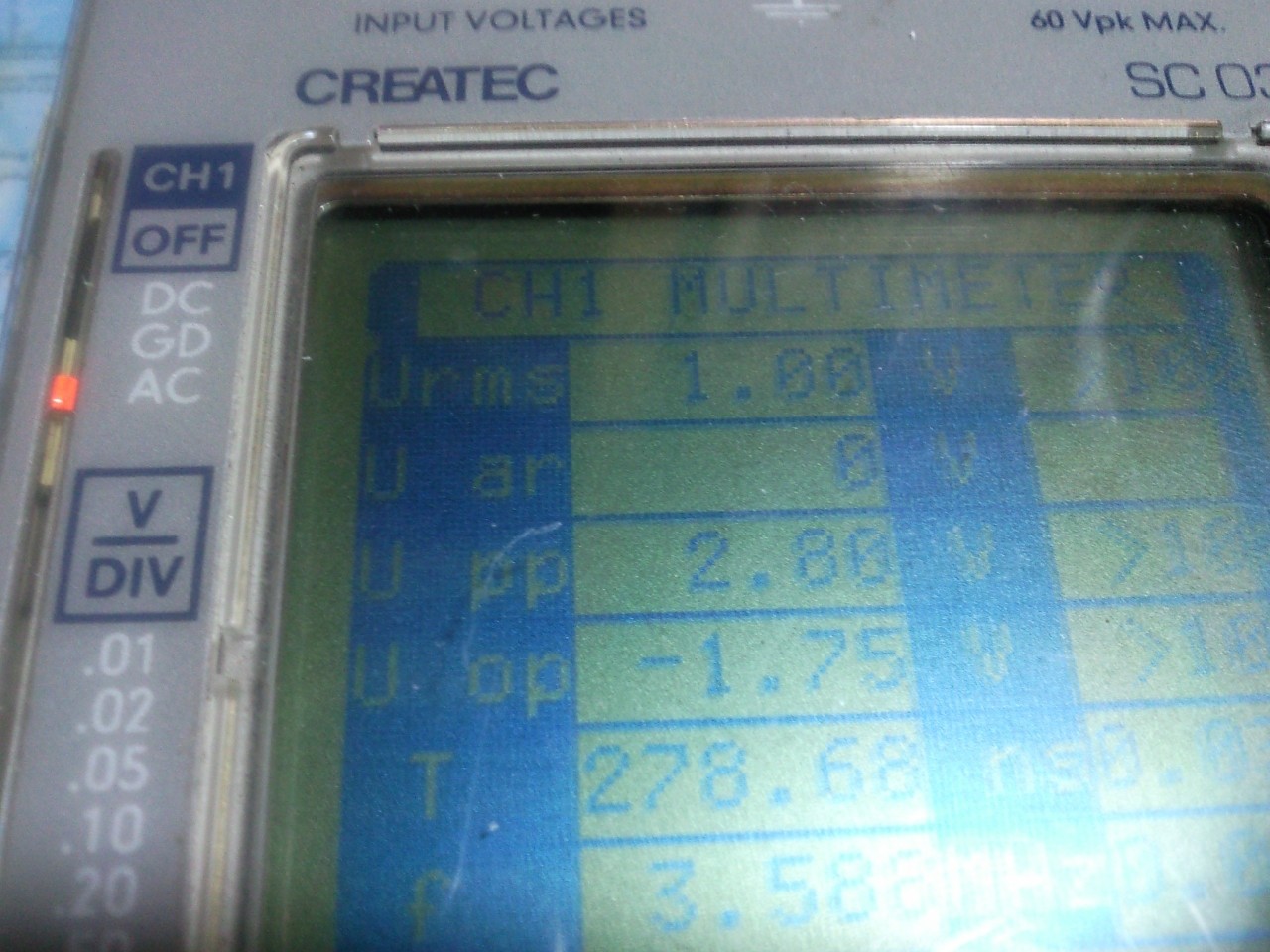
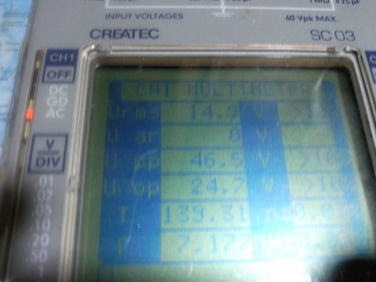
If that is not the problem, you may want to get [email protected]
involved.

73,
Don W3FPR

On 9/27/2010 6:39 AM, Igor Lána wrote:
> Hello Don,
> thank you for advice.
>
> I check L9 and L10 again a it looks like good
> (http://ok1tgi.nagano.cz/obrazky/K1/L9_L10.jpg) - 28 turns.
> I check all condensators on FB for 80m band and everything is OK.
>
> I made new measuring.
> I removed out the DRV-ground jumper and checked waveshapes on DRV and PA
> pads.
> Power supply 13,8V/3.5A, output power 0.1W, dummy load 15W Nagoya 0-500MHz.
> Oscilloscop Createc SC-03, 9MHz
> Current was 0,45A on 40m, 0,98A on 80m.
>
> DRV 7MHz (150ns, 1V): http://ok1tgi.nagano.cz/obrazky/K1/DRV_7MHz.jpg
> DRV 3.5MHz (150ns, 2V): http://ok1tgi.nagano.cz/obrazky/K1/DRV_3MHz.jpg
> PA 7MHz (150ns, 5V): http://ok1tgi.nagano.cz/obrazky/K1/PA_7MHz.jpg
> PA 3.5MHz (150ns, 20V): http://ok1tgi.nagano.cz/obrazky/K1/PA_3MHz.jpg
>
> Yes, there isn't little bit nice sinusoid. But bigger surprise was measuring
> in multimetr mode.
>
> DRV 7MHz = 650mV rms: http://ok1tgi.nagano.cz/obrazky/K1/DRV_7MHz_mm.jpg
> PA 7MHz = 3.6V : http://ok1tgi.nagano.cz/obrazky/K1/PA_7MHz_mm.jpg
> DRV 3.5MHz = 1V (?!): http://ok1tgi.nagano.cz/obrazky/K1/DRV_3MHz_mm.jpg
> PA 3.5MHz = 14.9V (!!): http://ok1tgi.nagano.cz/obrazky/K1/PA_3MHz_mm.jpg
>
> This is strange values, isn't it ?
>
> But the biggest mystery - see lowest line on PA 3.5 MHz multimetr PA
> measuring - there is 7.177 MHz !!!
> I also made short checking with better oscilloscop (200MHz) at work on
> friday. And it showed me the same problem. But I didn't have dummy load and
> I thought that is the reason.
>
> Is the PA over-drived ? Does it work in class C correctly ?
>
> I checked "POWER" signal on pin 6, connector J1
> RX 2.2 V for both bands. TX 3.5MHz = 2.94V DC, 7Mhz = 3.17V DC.
>
> L1-L8 are adjusted for the best RX. Attemps in TX are complicated. On 80m I
> can't setup higer otput that 0.5 W because current is too high. On 40m I can
> adjust maximum 1W output with 2.0 "menu level".
>
> Now I don't have any ideas.
>
> Igor OK1TGI
>
> ----- Original Message -----
> From: "Don Wilhelm"<[email protected]>
> To: "Igor Lána"<[email protected]>
> Cc:<[email protected]>
> Sent: Sunday, September 26, 2010 7:33 PM
> Subject: Re: [Elecraft] K1 80/40 tx problem
>
>
>>   Igor,
>>
>> The waveshapes are normal.  They will not be anything like a sine wave
>> coming out of a mixer, but the fundemental RF voltage is still present, so
>> the waveform will be cleaned up by the bandpass filters and the PA Low
>> Pass Filter.
>>
>> Since you have excessive current draw, the first place to look is the Low
>> Pass Filter on the 2 band board.  Are the capacitors correct?  Are the
>> number of turns on the toroids correct?  Count the turns carefully,
>> counting each turn that goes through the center of the core - a straight
>> wire through a toroid is one turn, a full wrap around the core is two
>> turns.  Failure to realize that fact is a common builder error.
>>
>> 73,
>> Don W3FPR
>>
>> On 9/26/2010 12:06 PM, Igor Lána wrote:
>>> Hello friends,
>>> I built a kit K1 80/40. Everything was no problem. All values of
>>> resistors
>>> and DC voltages were OK. But in chapter 9, part "Band 1 Allignment",
>>> transistor Q7 has been melted (2W at 80 m band).
>>> I changed it and after that I measured current -  0.1 W on 3.6 MHz
>>> current
>>> is 1.1A! On 7 MHz, is slightly better - 0.1W  is 0.4 A but the 2W is 1.3
>>> A.
>>> After several attempts to find mistake, I tried to use the "Signal
>>> Transmitter tracing" with DRV-ground jumper. Instead of RF Probe  I used
>>> the
>>> old oscilloscop in multimetr mode. I performed the measurements to the
>>> point
>>> 15. All values looked like okay, but from the point 10, I watched the
>>> unstability.
>>> I switched oscilloscop to the measurement curve mode. And on OSC it is
>>> not
>>> pure sine wave. The point of MIX has been very vibrant.  ATTN is clean. I
>>> do
>>> not know if  the problem is on 6-7 intputs U8 or output 4.
>>> Please, see videos of measuring on youtube.
>>> ociloscop 150ns time raster: http://www.youtube.com/watch?v=fYTOw9DWfKI
>>> ociloscop 50ns time raster: http://www.youtube.com/watch?v=9mUunLQdBuU
>>> ociloscop-multimeter: http://www.youtube.com/watch?v=oFaKCssXsA
>>> In every video first part is on ATTN, second on OSC, and the third on
>>> MIX.
>>>
>>> Please, do you have some recommendations how or where to find the error?
>>> Can Xtal X6 defective?
>>>
>>> Thanks
>>> 73 Igor OK1TGI
>>>
>>> ______________________________________________________________
>>> Elecraft mailing list
>>> Home: http://mailman.qth.net/mailman/listinfo/elecraft
>>> Help: http://mailman.qth.net/mmfaq.htm
>>> Post: mailto:[email protected]
>>>
>>> This list hosted by: http://www.qsl.net
>>> Please help support this email list: http://www.qsl.net/donate.html
>>>
> ______________________________________________________________
> Elecraft mailing list
> Home: http://mailman.qth.net/mailman/listinfo/elecraft
> Help: http://mailman.qth.net/mmfaq.htm
> Post: mailto:[email protected]
>
> This list hosted by: http://www.qsl.net
> Please help support this email list: http://www.qsl.net/donate.html
>
______________________________________________________________
Elecraft mailing list
Home: http://mailman.qth.net/mailman/listinfo/elecraft
Help: http://mailman.qth.net/mmfaq.htm
Post: mailto:[email protected]

This list hosted by: http://www.qsl.net
Please help support this email list: http://www.qsl.net/donate.html