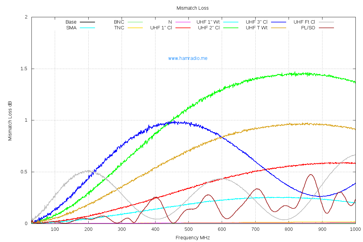
This compares well enough with my measurements...

http://www.hamradio.me/graphs/connectors/UHFConnectorGraphs/Mismatch-Loss_1000.png
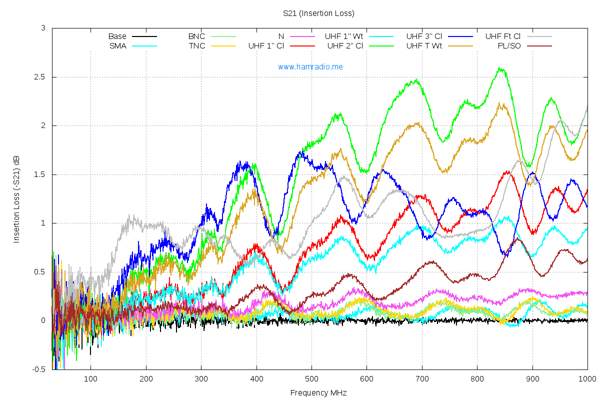
http://www.hamradio.me/graphs/connectors/UHFConnectorGraphs/Insertion-Loss_S21_1000.png


Some of the longer UHF "barrels" show the repeating characteristic you
observed which I assume is when the "different" transmission line is
about 1/2 wavelength long.

John, kx4o

On 4/25/12 7:09 PM, Alan Bloom wrote:
Since two N or UHF adapters were used, I assume the loss per connector
is half the total. The vertical scale was .1 dB/division, so I estimated
the insertion loss to the nearest .01 dB or so:

              --------- Type N --------   ---------- UHF ----------
FREQ (MHz)  TOTAL  LOSS PER CONNECTOR   TOTAL  LOSS PER CONNECTOR
1.8         0 dB   0 dB                 0 dB   0 dB
30          0      0                    0      0
100         0      0                    0      0
150         0      0                    0.02   0.01
200         0      0                    0.03   0.015
450         0      0                    0.18   0.09
600         0      0                    0.26   0.13
900         0      0                    0.66   0.33
1000        0.05   0.025                0.8    0.4
1300        0.1    0.05                 0.86   0.43
1600        0.05   0.025                0.5    0.25
2000        0.05   0.025                0.02   0.01

Insertion loss increases until about 1300 MHz, and then starts to
decrease until it is almost zero for the UHF connector at 2 GHz!  At
that frequency, the connectors are about 1/4 wave long (1 inch,
assuming .66 velocity factor), so I assume that the two adapters are
providing a conjugate match to each other. This confirms my assumption
that the insertion loss is due to reflections (impedance mismatch), not
absorption (true power loss).
______________________________________________________________
Elecraft mailing list
Home: http://mailman.qth.net/mailman/listinfo/elecraft
Help: http://mailman.qth.net/mmfaq.htm
Post: mailto:[email protected]

This list hosted by: http://www.qsl.net
Please help support this email list: http://www.qsl.net/donate.html