Excellent post, John. You don't mention that there is even more useful
information about this on your web site.
I have always thought it would be very useful for Elecraft to post "App
Notes" of this kind about all their mini-kits. I know several people who
have built them seemingly to satisfy their kit addiction, but then toss
them in a drawer and never use them. There is plenty of information
around about how to use them, but I think it would be very helpful to
see them used almost in a tutorial fashion as you have done here.
Specific hook ups and tests on Elecraft gear with the noise generator,
2-tone generator, etc.
Many of us have used equipment like this over decades, but Elecraft has
introduced whole new generations to ham radio who could really benefit
from knowing how to routinely use this test equipment, and enjoy a new
aspect of the hobby at the same time.
I think the work you show on your web site could be the first of these
App Notes.
Eric
KE6US

On 8/24/2013 5:28 AM, John Oppenheimer wrote:
How many of you have an Elecraft DL1? It's an amazing piece of test
equipment for only $26 when coupled to an accurate DVM.
The DL1 is a simple 50 ohm dummy load with a peak detector diode. The
load on the diode is the input impedance of the voltmeter, normally
10 Meg Ohm, which results with a rather flat 0.25 Volt diode loss.
One use is to measure coax loss along with the KX3. The KX3, having an
active power control, has a very stable and repeatable power output.
The Fluke 87V has four significant digits when measuring 10 watts. The
KX3 output is repeatable, using the 87V AutoHOLD feature, within +-2 LSB
digits (+-0.02V) resulting with a resolution of about 0.022 dB.
Measuring coax requires two measurements, therefore, the coax loss
computation is within about 0.044 dB.
Some additional loss error may be caused by the DL1 50 ohm RF impedance.
I suspect that the DL1 is well within 2% in the HF region, probably
within 1%.
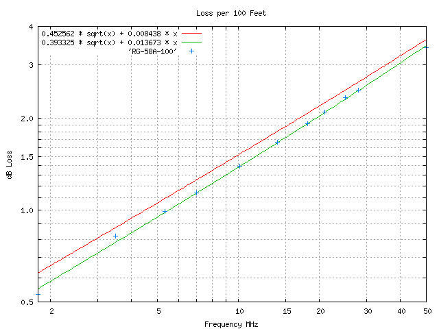
As a test, I measured and plotted a 100 foot piece of RG-58A/U. And
solved for K1, conductor loss, and K2, dielectric loss, constants.
Loss = K1 * SQRT(F) + K2 * F
http://www.kn5l.net/Elecraft/DL1RG58Loss.png
The Red line is for constants computed from
http://vk1od.net/calc/tl/tllc.php. The Green line is a least squares fit
to the measurements. The Blue ticks are the RG-58A/U measurements using
the KX3, DL1, and 87V.
John KN5L
______________________________________________________________
Elecraft mailing list
Home: http://mailman.qth.net/mailman/listinfo/elecraft
Help: http://mailman.qth.net/mmfaq.htm
Post: mailto:[email protected]
This list hosted by: http://www.qsl.net
Please help support this email list: http://www.qsl.net/donate.html
______________________________________________________________
Elecraft mailing list
Home: http://mailman.qth.net/mailman/listinfo/elecraft
Help: http://mailman.qth.net/mmfaq.htm
Post: mailto:[email protected]

This list hosted by: http://www.qsl.net
Please help support this email list: http://www.qsl.net/donate.html