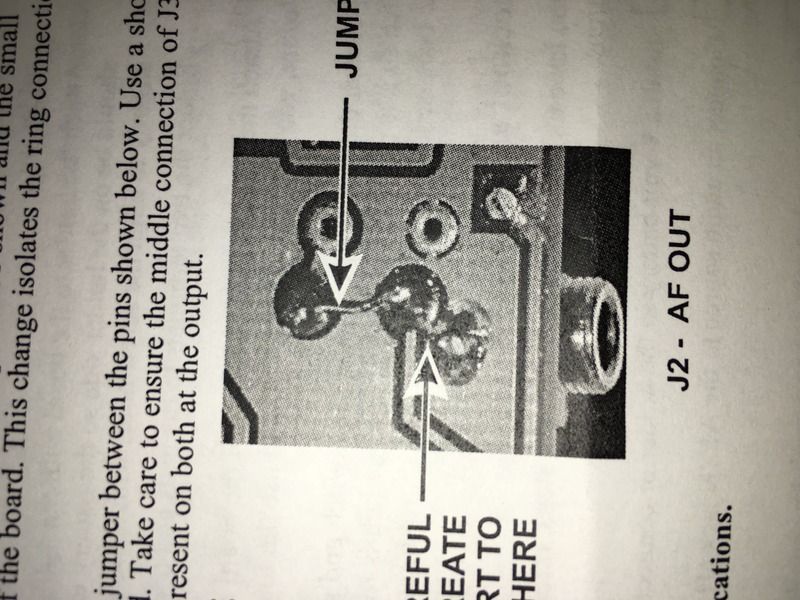
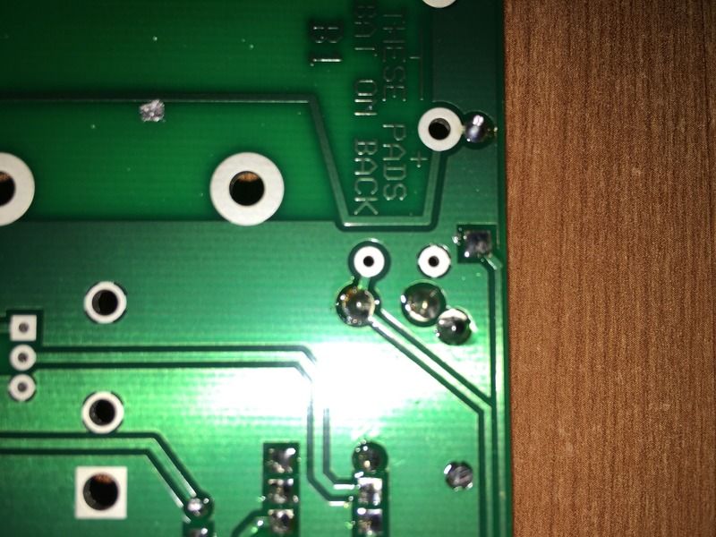
I'm building the Elecraft AF-1 Audio Filter. My PCB has "REV A" printed lower
left. I see pictures of a "REV XA" on the web, but mine definitely say "REV
A" only. The "REV B" manual
http://www.elecraft.com/manual/E740102%20AF1%20Active%20Audio%20Filter%20Rev%20B.pdf
shows that modifications are needed at both J1 AF IN and J@ AF OUT jacks, I
did the J1 - AF In mod, but see that my PCB is different than that shown in
the REV B manual.
The manual show this
http://i29.photobucket.com/albums/c290/cbjesseeNH/AF-1-2_zpsfzrvndif.jpg

My PCB board looks like this
http://i29.photobucket.com/albums/c290/cbjesseeNH/AF-1-1_zpsxstny3c8.jpg

The reason for the mods are given as:

The PC Board traces for the AF1’s audio input jack J1 and output jack J2
were wired to only the “ring” connection of the stereo tip-ring-sleeve
jacks.  If you are using stereo mini-phone cables this will not cause a
problem, but a mono plug will not provide any audio into the AF1 as the J1
“tip” is unconnected.

Additionally, the AF1 J2 Output jack should have the tip and ring
connections wired together so that stereo headphones work correctly.

Saturday and Elecraft is closed, so I thought I'd ask advice here, thanks.

BRET/KC1CJN


--
View this message in context:
http://elecraft.365791.n2.nabble.com/AF-1-Rev-A-J2-AF-Out-Looks-Different-tp7618771.html
Sent from the Elecraft mailing list archive at Nabble.com.
______________________________________________________________
Elecraft mailing list
Home: http://mailman.qth.net/mailman/listinfo/elecraft
Help: http://mailman.qth.net/mmfaq.htm
Post: mailto:[email protected]

This list hosted by: http://www.qsl.net
Please help support this email list: http://www.qsl.net/donate.html
Message delivered to [email protected]