> From: Chris Albertson [mailto:albertson.ch...@gmail.com]
> On Mon, Jun 24, 2019 at 11:33 PM John Dammeyer
> <jo...@autoartisans.com>
> wrote:
>
> > I have some CAN bus experience if you have any questions.
> > John Dammeyer
>
> One thing I don't know is if one transceiver chip works better than
> another.   I can read the spec sheets but have no practical experience.
> I planned to use the MCP2551 in combination with the STM32
> microcontroler's
> built-in CAN controller.    But the TJA1050 seems like it will work too.
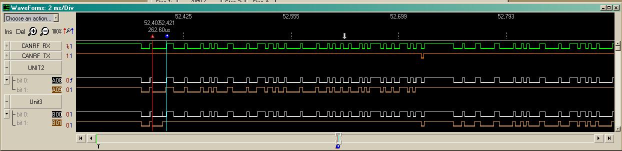
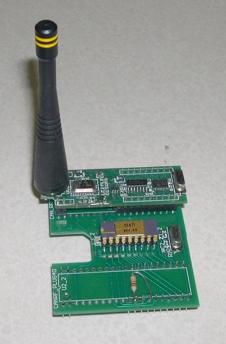
Cool project.

The biggest difference between CAN transceivers out there is some are designed
for 3.3V systems and others for 5V.  Originally it was 5V so that put CAN_H at
2.5V and it went up to about 4.V while CAN_L was at 2.5V and dropped to about
1.0V.

The 3V devices can still pull CAN_L down to 3V but of course can't pull CAN_H
up any higher than about 3V.  That still makes a 'dominant' signal 2V compared
to 0V for recessive.  Whereas the 5V devices have more like a 3V dominant
voltage between signal pins.

Do remember, that CAN is a 3 wire system even though it appears to work with
only two wires.  It's not truly differential like RS422 or RS485.  For
differential the current actually changes direction through the termination
resistors at each end of the bus.  With CAN there is no current flowing during
the recessive bits and bus idle.    That's so you can have CSMA/CR  (Carrier
Sense, Multiple Access with Collision Recovery)

And not using a common ground between all nodes means the likelihood of Common
mode noise or even voltage drops make blow up your transceiver.  Can't stress
that enough.

>
> There are many low-cost MCP2515/MCP2551 breakout boars on eBay.   I plan
> to
> use them to prototype but then design a custom PCB for both
> Raspberry Pi and STM32.

I've used the MCP2510 and then MCP2515 in a lot of different projects.  Here's
an example of bitwise arbitration using my CANRF which used 916.5MHz ON OFF
KEYING for the bitwise arbitration.  The logic analyzer in this picture was
connected to the 3 different wireless modules
http://www.autoartisans.com/canrf/images/rf-arb.jpg
This was a test board where the on board MCP2510 was replaced with a Microchip
Beta Test version of the MCP2515.
http://www.autoartisans.com/canrf/images/MCP2515.JPG
which plugged into this PIC12 series processor module for the yard light
protocol.
http://www.autoartisans.com/canrf/images/RFPROJ1.JPG


>
> This is a motion control system not unlike LinuxEMC.  Our design uses a Pi3
> (now Pi4) as the central motion planner then we have some number,
> perhaps
> as many as 20 STM32 connected by CAN Bus and then these connect to the
> motors.  We will use a mix of steppers, BLDC and PWM controlled DC motors
>  About 24 axis in all.   So We want to run CAN to distribute the data.

My other question, and where I've seen the most failures have to do with which
High Level  Protocol (HLP)  you are using?

Or do you plan to roll your own?

If you plan to roll your own there is only one really serious issue to watch
out for.  It's absolutely forbidden, with serious consequences if you do, to
allow different devices to transmit identical CAN IDs onto the bus.
Even with this project:
http://www.autoartisans.com/rings/Barge1a.jpg
Where I rolled my own HLP, the messages transmitted were still unique with over
150 nodes per each of 10 CAN channels.

I'd look at implementing a subset of CANopen since you can have up to 127
devices which exceeds the physical drive capability of the bus.  The
infrastructure for motor control is already in place so you could copy that but
keep the overall system simple.
John

>
> This is for a humanoid robot.  The first version models a a person in a
> wheelchair.  The hands will be able to do anything a person seated at a
> table could do.  We are using a pair of prothetic hands that are more
> commonly used for amputees but in this case they are attached to robot
> arms.   There are ten motors in the hand alone, one for each finger
>
> Here is the overall application.  It is an X-prize contest.
> https://avatar.xprize.org/prizes/avatar
>
> We do two levels of prototype.  The first with cheap and simple stepper
> motors.  Then later with more powerful BLDC motors running miniaturized
> variable speed transmissions.   A human shoulder has three degrees of
> freedom and needs three motors, six for two shoulders.    The challenge is
> to fit 6 motors and all those bearing in such a small space.   But the
> simple prototype comes first.    I just finished the the basic mechanical
> design and you can see it here https://a360.co/2N2ynIB
> The hand sed for prototype is here https://openbionicslabs.com   The arm
> that conects shoulder to hand comes next.   About 4 years of work remain
> for the team
>
> If this looks like an interesting project let me know, there is room for
> more.
>
> How is this related to LinuxCNC?    Obviously there are many parts to be
> made.
>
>
>
> --
>
> Chris Albertson
> Redondo Beach, California
>
> _______________________________________________
> Emc-users mailing list
> Emc-users@lists.sourceforge.net
> https://lists.sourceforge.net/lists/listinfo/emc-users


_______________________________________________
Emc-users mailing list
Emc-users@lists.sourceforge.net
https://lists.sourceforge.net/lists/listinfo/emc-users