On Mon, 07 Feb 2011 13:30:24 -0500
rickman <[email protected]> wrote:
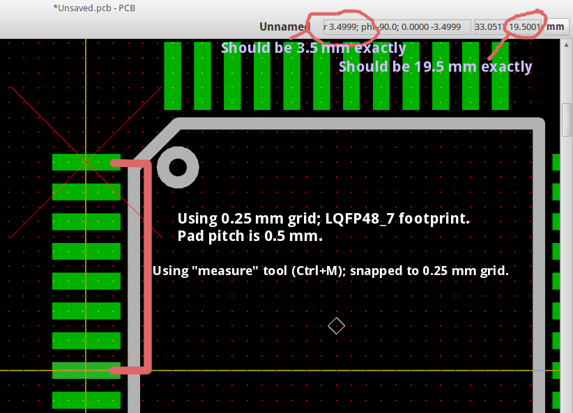
> On 2/7/2011 11:21 AM, Peter C.J. Clifton wrote:
> > On Feb 7 2011, rickman wrote:
> >
> >> The real question is does the current method cause any problems?
> >> When this was discussed a few months ago the answer was "no".  So
> >> why worry about 1 part in a million error?  Engineering is all
> >> about tolerances.
> >
> > We do have some problems with rounding and 45-degree lines, but I'm
> > not convinced metric units internally is a magic bullet for that.
> >
> > Display of accurate coordinate in metric IS a problem though.
>
> How so?  I thought the dimensions in these tools are done with 10
> microinch resolution.  Isn't that enough for anything on the visible
> horizon?  Actually, I wouldn't think the display is the problem, but
> rather the problem would be generation of rounded data for output
> such as Gerber files.  What are people using this software for that
> requires better than 10 millionths of an inch accuracy?

I often see some odd values due to inexact conversion to millimeters in
pcb.  It slows me down when I'm trying to draw a footprint since I have
to constantly round the numbers in my head; while easy, you have to be
constantly doing this every time you click a point and it is a waste of
time.

See a simple example on the screen shot:
<http://gibibit.com/upload/2011-02-07_pcb_mm_error_display.png>.
Here I used the "measure" tool to measure a distance between two points
on a 0.5 mm grid, but the displayed result is not correct.  Sure,
mathematically it is extremely close to the correct value, but for my
brain to convert this each time I glance at the position/measurement
display in pcb, it does accumulate since I refer to the display so
frequently.

Regards,
Colin


_______________________________________________
geda-user mailing list
[email protected]
http://www.seul.org/cgi-bin/mailman/listinfo/geda-user