> DJ - If you redo the pcb - please consider reworking the physical layout
> so all the mains stuff is physically separated from the logic-level
> stuff that people might come into contact with.  A mains wire breaking /
> falling out of the screw terminal and touching control wiring can have
> interesting consequences.
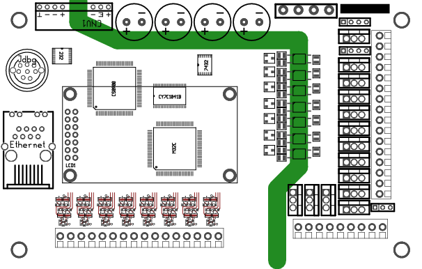
It's only a 24vac system on the "mains" side, not 120vac.  Well below
the ouch threshold.  These are the same wires that are normally strung
throughout the house, hooked to flimsy thermostats and such.

But on the new one, the terminal blocks are all along the edge, with
the circuitry behind them and the wires on the "outside".  This is the
layout so far (no schematics yet, just fiddling with component sizes):
http://www.delorie.com/house/furnace/furnace2.png

The green line is the 6mm gap between the 24vac side and the 5vdc
side.  All 5v-side connections will have multiple ESD blocks on them.
When I get to that point, I'll probably start posting schematics as I
develop each module, for feedback and insight.

I've talked with Digikey and they expect to get some new top-access
terminal blocks (weidmuller LSF-SMT 3.5mm vertical) by mid-year.  That
will let me put them closer to the edge and reclaim more board space
for logic.  I'm hoping the straight-in connection will reduce the
number of stray touches during setup, not that I put any traces on
those parts of the board.

I'm also thinking this should be a 4 layer board.  The extra ground
and power planes will also help protect against ESD and inducted
spikes both by providing the capacitive planes and avoiding
antenna-like ground paths, and lets me hide the AC "mains" inside the
board.

And the alternistors have isolated tabs too.