Tim and others,

Regarding the depiction of protein cavities as per:
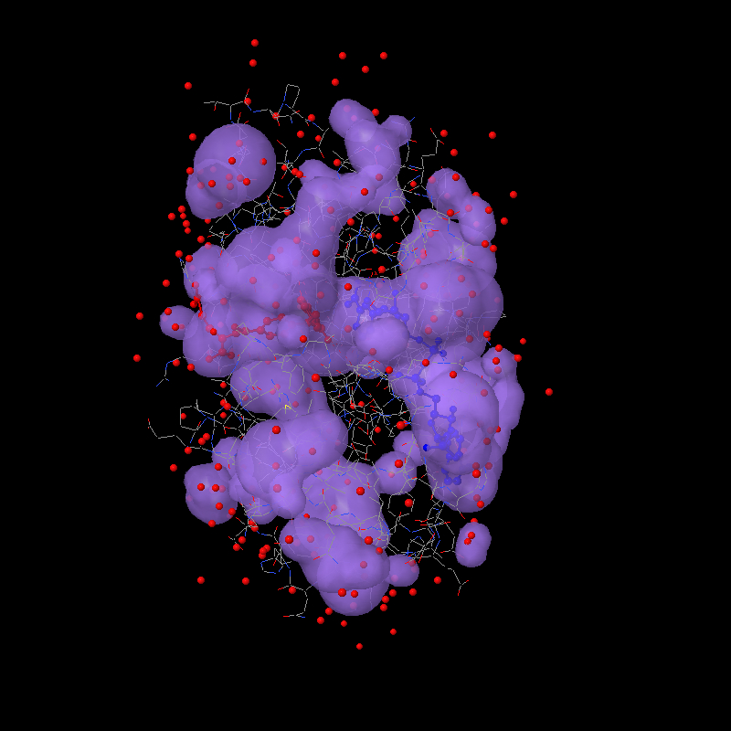
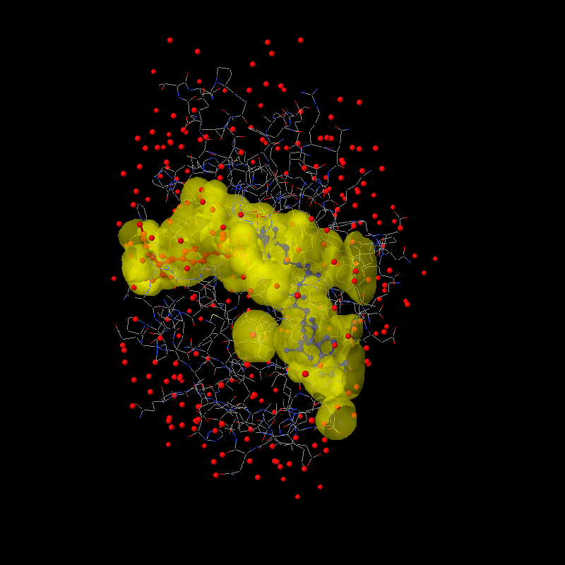
http://www.biochem.ucl.ac.uk/~roman/surfnet/examples/3dfr_site.html

Good news! I tried a bunch of ideas this weekend, and then this morning
I hit on the solution: The way solvent surfaces are generated in Jmol is
probably unlike any other program. A grid of values is calculated just
like for a molecular orbital, and then that grid is processed for the
isosurface through the value 0. So values on the inside of the surface
are < 0 and values on the outside are > 0. After quite some trial and
error, I finally realized this morning that the key is those positive
"outside" values. What we need to do to render cavities is (a) identify
all grid points that have positive values AND are within the overall
"envelope" of the protein and (b) use the value that is there for the
RADIUS of a sphere at that point. That's your "foam filling"! Since each
value measures the distance from the grid point to the nearest surface
point, placing a sphere of that radius at that point perfectly "fits"
the hole. It isn't important to fill a cavity with the perfect sphere --
the end goal is to turn around and use these grid-based spheres for
ANOTHER solvent-surface calculation, this time as though we were trying
to find the solvent surface around those "cavity" points.

So then the other trick is how to identify just the cavity points and
not all the other points far out from the molecule. The solution here
uses the geosurface business that I set up. Actually, I sat down and
cleaned up dots and geosurfaces so that their calculation could be used
more generally.  Here's how we identify the "envelope" of a protein:
First we create a "dot surface" 10 angstroms out from all atoms. What
you find is that only the outer atoms contribute to this -- all the
other atoms are hidden. Then the distance from each "foam cavity sphere"
to the nearest surface dot is measured. If this distance is < 10, then
we can throw out the point, because the point must be "outside" the
molecule. But if the distance is > 10, then that point must be "within"
the molecule. We keep it.

What do you know? Perfect rendering of cavities as if they themselves
were atoms. Or, at least I hope you think so. Here's a jpg to get your
appetite whetted:

http://www.stolaf.edu/academics/chemapps/jmol/docs/misc/3dfr-a.jpg
http://www.stolaf.edu/academics/chemapps/jmol/docs/misc/3dfr-b.jpg

The first was done using:

load =1dfr;select protein;spacefill off;wireframe on;color (ndp)
blue;color (mtx) red

isosurface select(protein) ignore(not protein) cavity 10 1.4
color isosurface translucent 4
write image 800 800 1dfr-a.jpg

The second focuses on the two ligands and uses:

isosurface isosurface1 select(protein and within(4.0, not protein))
ignore(not protein) cavity 10 1.2
color isosurface translucent 6 yellow
write image 800 800 1dfr-b.jpg

The two parameters  are the envelope radius (10 effectively defines the
radius of the outer "pores" that define a cavity) and the minimum cavity
radius (1.2 Angstroms about the size of a water molecule). These
parameters can be tweaked. Maybe Tim, you can help me settle on some
reasonable defaults.


Bob


-------------------------------------------------------------------------
Take Surveys. Earn Cash. Influence the Future of IT
Join SourceForge.net's Techsay panel and you'll get the chance to share your
opinions on IT & business topics through brief surveys-and earn cash
http://www.techsay.com/default.php?page=join.php&p=sourceforge&CID=DEVDEV
_______________________________________________
Jmol-developers mailing list
[email protected]
https://lists.sourceforge.net/lists/listinfo/jmol-developers