http://denki.world3.net/avr_rescue.htmlATmega48/88/168 incorrect fuse rescueWhile developing the Retro Adapter I managed accidentally lock a couple of ATmega168s by programming the fuse bit which disables RESET, thus disabling serial program downloading too. The AVR was attached to a keypad matrix which caused the programmer to accidentally set it. In order to recover an AVR and restore the SPI programming interface you need to use High Voltage Programming mode. Unfortunately HV programmers are not very common, so I decided to look into making one. While I still plan to make a full programminger in the long term, for now I have adapted Jeff Keyzer's Arduino based HV programmer to use an ordinary ATmega8. The design is fairly simple and easy to make on matrix board or even breadboard. It also works with the ATmega48/88/168 family. The design could easily be adapted to rescue almost any other AVR. All that is required is the program code updating with the correct fuse values and if necessary the wiring altered to suit. My thanks go to Gustavo Spadari for pointing out a bug in the code and testing with an ATmega48V.
Hardware
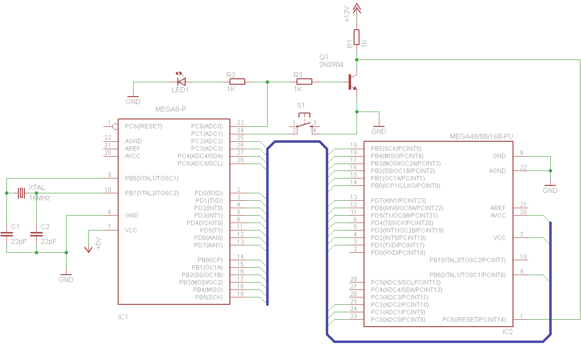
Note that the 16MHz xtal is not required. The code work work at 1MHz on the internal RC oscillator.
Connection map:
In the schematic the two AVRs are connected directly. Adding 1KΩ resistor to every line will provide some protection for the ATmega8 against inserting the target AVR incorrectly. The only line which should not have a resistor is the one from PB0 to Vcc/AVcc. My matrix board build omitted them. When powered on, the LED lights up to indicate that the device is ready. When the button is pushed it dims for approximately 1 second while setting the fuses, then comes back on to signal that the programming cycle is complete. The circuit requires a dual 5V and 12V power supply. A DC-DC converter could be used to generate 12V, as only a very small amount of current is required to hold the RESET line of the target AVR at 12V. High voltage programming works by holding the RESET line at 12V. The ATmega8 controls the programming process by first powering up the target AVR (the mega48/88/168 in the schematic) and then applying 12V via the transistor. In the schematic the ATmega8 is clocked by a 16MHz crystal, but in practice any crystal or even the internal RC oscillator should work (however they are untested). The code includes some delay loops, however they are only minimum time delays so it should not matter if they run for longer than expected.
FirmwareThe code is based on Jeff Keyzer's Arduino code, but converted to ordinary C code that uses AVR-GCC. This removes all dependencies on the Arduino hardware and makes things a lot clearer and easier to work with for those of us who don't use that platform. It would not be too tricky to extend the code to other AVRs or even add a USB/RS232 interface to turn it in to a full programmer. However, I am instead planning to make Jacob Here's USB high voltage programmer and producde a PCB for it, as it is already more advanced and supports a number of AVRs. Firmware: AVR-Rescue-0.2.lzh / AVR-Rescue-0.2.zip
| |||||||||||||||||||||||||||||||||||||||||||||||||