Hola:

Yo he montado algunos. Me han funcionado los que he hecho a base de dividir
la frecuencia por cuatro con un integrado. Lo quitar la frecuencia imagen
haciendo el desfase de 90 grados a base de un condensador no lo he
conseguido (el Tiny SDR). Pienso que hay que hacer un montaje más cuidado.
El SDR que va muy bien es el la revista ELEKTOR que te lo ponen en casa por
113 €.
Te adjunto el tiny y el de integrados.
Abrazos Manolo Santos


*Software Defined Radios*

*Lietuviškai <http://www.qrz.lt/ly1gp/SDR/indexlt.html>*
------------------------------

*TinySDR for 80m band*

My first look at the SDR technology was not very impressive - FlexRadio
SDR-1000 was too complicated to build and too expensive to buy, but second
one - SoftRock was another story: simple, clear principles and easy to
build. I decided - SDR will be my next project. Several years ago I have
made several direct conversions receivers and transceivers. Most of them
were V. Poliakov RA3AAE designed, but also some from QST or other
periodicals. I think radio amateurs paid not enough attention to this type
of receivers until this time, SDR get them back.

My decision was to start from the very basic project included my tiny
experience in direct conversion.

*Schematics*

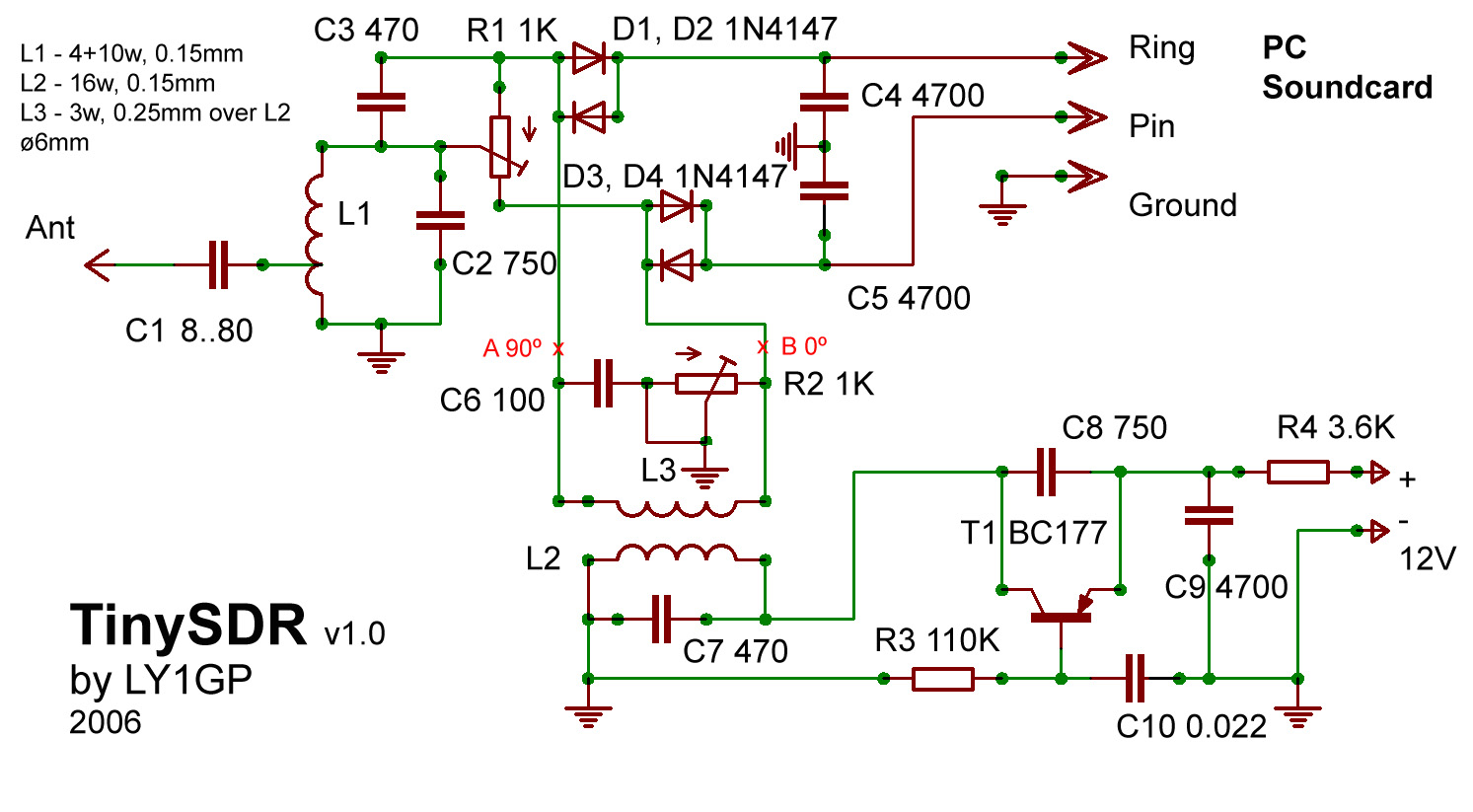
<http://www.qrz.lt/ly1gp/SDR/tinysdr.jpg>

L1C2 - its the most simple band pass filter, tuned to the necessary
frequency. To achieve better selectivity it would be better to have more
complex band pass filter. There are many different variants on the internet
to choose. It is interesting, that it is possible to make a receiver even
without any band pass filter, but due to simplicity this not recommended.

Signal from antenna goes to double mixer (diodes D1-D4), at the same time
signal from VFO is provided with different phases - 0 and 90 degrees. Just
after mixer signal goes to PC soundboard. There are no low frequency
amplifiers before PC plug. Audio amplification is done by PC soundboard,
therefore it is recommended to use PC microphone jack, not Line-in.

VFO is made using the simplest circuit I can remember. Transistor T1 is of
any type p-n-p one. Max working frequency is only important factor.

*Materials*

Diodes any type of 1N4147, 1N4148, 1N4154, also is it possible to use exUSSR
made  KD503, KD522, KD521. L1 has 4+10 turns of 0.15 mm copper wire (I used
silk covered, but this not necessary), 4 from the ground. L2 - 16 turns of
the same wire, L3 3 turns of the 0.25 wire on the top of L2.

C1 value depends on the antenna used and can be selected for best
performance. Also can be avoided totally.

Phase transformer values depends on the receiver frequency and should be
calculated. Formula: C6=1/(2*pi*f*R), where f - VFO frequency, R - R2
resistor/2. Presented values are for 80 meter band.

Key point for the receiver performance is PC soundboard. Therefore
soundcards recommended for the SDR-1000 (M-Audio Delta 44 and Delta 66)
would be best performers, also several Creative products would be
acceptable. But I used this receiver with several onboard audio chips
(mainly AC'97), and they are OK. One of the main aspects is soundcard 16-bit
or 24-bit, 16-bit allow to use 48 kHz range of band, 24-bit - 96 kHz -
almost full old 40 meter band with same VFO setting.

*Tuning*

Some tuning is required. At the first with the help of oscilloscope tune
your band pass filter, after with frequency counter - VFO for the selected
frequency - this will be your band center. These are not critical you can
tune receiver for highest sound and necessary ham radio station after second
step.

Second step is to make phase transformer give necessary difference in
phases. Connect twin input oscilloscope to points A and B, and choose the
value of the R2 until you will have circle on the screen. Perfect circle
means 90 degrees difference. I have read several times on the internet and
in periodicals that it is impossible to make SDR based on analog devices,
because 90 degrees difference with less than 1 degree can not be achieved.
This could be true for high performance receivers (our is not such), and
today we have software which can correct phase differences.

First working prototype:

----------------------------------------------

Couple of recordings (15m band dipole, industrial site):

ER1TA <http://www.qrz.lt/ly1gp/SDR/er1ta.mp3>

UT5MD <http://www.qrz.lt/ly1gp/SDR/ut5md.mp3>


I would recommend to select Rocky software due to compensating mechanism
implemented or PowerSDR, which is used with SDR, but any other is OK also.

Rocky <http://www.dxatlas.com/rocky/> - in my opinion best balanced
software.

PowerSDR <http://www.flex-radio.com/> - for SDR-1000.

------------------------------------------------------

ADDITIONS

*IMPORTANT! *For normal SDR reception with this receiver your PC should have
stereo microphone input. This is not usual for todays modern PC's with AC'97
chipset, only few of them have such option. This option have most IBM
ThinkPad notebooks, also some notebooks with Intel integrated sound, several
Intel PC mainboards, also mainboards with SounMAX integrated sound. More
advanced soundcards also provide stereo input. If your sound system do not
have such option you will be able to receive, but you will have LSB+USB
reception at the same time on both sides from VFO frequency.

Also it could be that line-in port is more sensitive to receive signals from
this receiver, which is usually stereo. I will provide simple op-amp
schematics to amplify signal and to use common line-in port.

*2007.01.23 *- to have maximum phase compensation - tune Rocky to strong
station, keep this for a while and it will tunes itself for best option.

*2007.01.25 *- To keep receiver as simple as possible I have tested
different VFO. If you have old PC mainboards, there could be clock
oscillator for 14.318 MHz, which allow you to make VFO for 20 meter band.

Tr2 - 10 turns primary with 0.25 wire and 2-3 secondary one. Oscillator any
type and company. Just frequency is important.


------------------------------

*ZetaSDR for 40m band*

This receiver is more sophisticated, but I tried to keep it also simple as
possible. I am actually not the author of the construction, I have seen such
(or very similar) schematics on the internet, but can not find it again.
Anyway, its also simple way to get SDR in action.

Main mixer is made using 74HC4052. YU1LM is not very satisfied about this
chip, because of unstability in higher frequences. I have not tested in full
HF range, but for 7 Mhz it is fully functional. *No winding here! :)*

*Finished construction*

*Schematics (click to get full size):*

<http://www.qrz.lt/ly1gp/SDR/zetaschem.jpg>

*PCB and partslist here <http://www.qrz.lt/ly1gp/SDR/zetapcb.zip>.*

PCB size 50 x 66 mm, one sided. Do not forget one unrouted wire.

 If no errors made - connect and enjoy.

Several RX examples (made just on occasion, antenna - W3DZZ multiband, AC'97
integrated sound):

9K2RA <http://www.qrz.lt/ly1gp/SDR/9k2ra.mp3>
IW0RZY <http://www.qrz.lt/ly1gp/SDR/iw0rzy.mp3>
HG3A <http://www.qrz.lt/ly1gp/SDR/hg3a.mp3>
HA1YI <http://www.qrz.lt/ly1gp/SDR/ha1yi.mp3>

----------------------------------------------

ADDITIONS

*2007.02.02* - Tasić YU1LM reported that 74HC4052 is good up to 10 Mhz.
Using it on higher frequencies result to worse image rejection.

*2007.03.15* - I will try to answer to several questions regarding this
construction, which I was asked several times:

   - Capacitors values in schematics are - in microfarads (uF) if number
   is with dot, like 0.022 is 0.022 uF (or same 22nF), others are in
   picofarads (pF) like 330 means 330 pF.
   - Clock oscillator frequency is not critical - you can choose any
   available oscillator which frequency divided by 4 goes into ham bands range.
   Instead of my used very often 14.318 oscillator could be found, which
   let you listen 80 m band (14.318/4=3.5798). These oscillators
   generally could be found in old mainboards, video cards, even hard drives.
   - I am frequently asked about the possibility to sell kits of this
   construction. If certain cases I can do that - kits will be without clock
   oscillator, and BNC connector and there is a problem with PCB - until this
   moment I made them at home which is not suitable for kit business, but if
   there will be many requests I will found a solution. In any case contact me
   concerning this.
   - I already started simple DDS project for this receiver to make it
   multiband.


Gintaras LY1GP, [EMAIL PROTECTED]


El día 16/10/07, SantiagoFélix <[EMAIL PROTECTED]> escribió:
>
>   Hola a todos.
> La gracia de los SDR (software defined radio) está en que la mayor
> parte del procesado (filtros o y mezcladores, por ejemplo) se
> implementan por soft y no por hard. Así, con un mínimo de
> componentes ("analógicos") se tiene máxima reconfigurabilidad de
> prestaciones, que, además, pueden ser todo lo soberbias que dicten
> los algoritmos de procesado. Por poner un ejemplo fácil, el filtrado
> que se puede llegar a aplicar con p.ej.: WinRad sería imposible de
> realizar con componentes analógicos.
> De hecho, y hablando de recepción, lo ideal sería muestrear las
> señales de antena directamente tras el filtro de sintonía frontal, y
> a partir de ahí, que el procesado implementado en DSPs, FPGAs, uP
> o/y PCs etc las trate.
> En plan cacharreo, la cosa promete, porque, como digo, bien
> diseñado, con pocos componentes, y software ya disponible, las
> prestaciones pueden ser tremendas.
> Pese a los PERSEUS, SDR-IQ, RFSPACE SDR-14, etc, y de que los kits
> también tientan (os recomiendo que le echeis una googleojeada a,
> p.ej.: SoftRock-40), llevo tiempo tentado de construir uno. Si
> alguien más se anima...
>
> Hasta pronto.
> ea3gly
>
>
>