thanks very much Jim, your right, I got my polarity mixed up a bit
there, thank you for your help with that
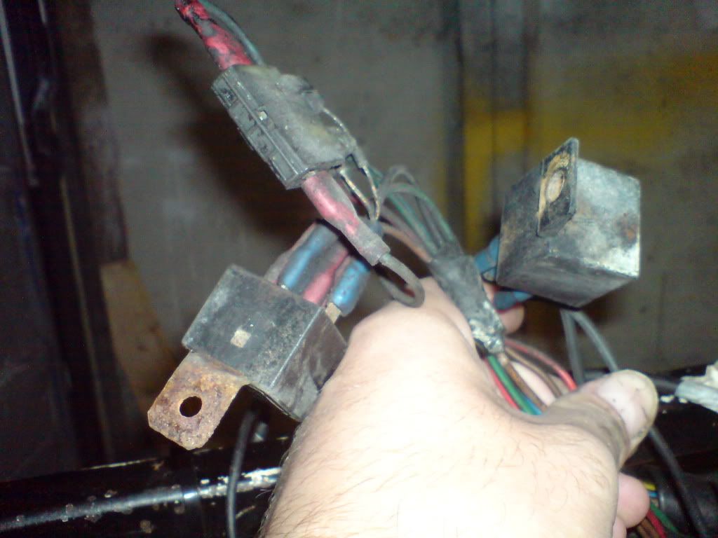
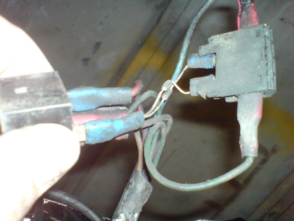
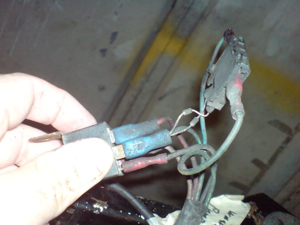
also thank you regarding the identification of the relay and the
diodes, I took another look at it this morning and it did dawn on me
that it was probably for the headlight flaps,

as it looks a bit untidy im hoping to replace the components involved
for new and make a better job of it, im assuming somewhere in the
build manual that it explains how to make up the diode wiring with
specs etc?
if so does anyone have a copy I could look at to see what is what?

also regarding the other relay, its wires go off up into the loom
within the bulkhead and im fairly sure it controls something to do
with the starting, is it known for a starter / ignition relay to be
added within the engine bay?
ultimately ill buy a new relay and wire it in with a proper holder but
I just like to know what it does, for peace of mind if nothing else

as ever your help is very gratefully received

regards

J king

On 23 Aug, 09:32, Jim Hearne <[email protected]> wrote:
>   The green wire from the distributor should got to the -ve (you
> mentioned +ve) terminal on the coil, if the car has a rev counter
> another green will leave the coil, possibly go through a suppressor and
> go to the rev counter.
> The black wire on the distributor should go to the +ve on the coil and
> then via the removed resistive lead to an ignition switched feed in the
> main loom.
> The brown on the distributor is connected to ground, preferably the
> battery earth not the engine.
>
> The relay with the 2 diode attached is almost certainly the one for the
> headlight flap motor.
> The diodes take signals from the main beam and dipped beam or sidelights
> (depends how it was wired) and operate the relay for the flap motor if
> either are on.
> The diodes are needed so that the relay is active if either of the 2
> circuits are active.
> The flap relay is a changeover so it always supplys power to one of 2
> terminals on the flap motor.
>
> The other relay may be for front fog or spot lights if you have them.
>
> Jim
>
> On 22/08/2010 21:55, jin wrote:
>
>
>
> > cheers Jim
>
> > ive checked that wire (not green though on account of the wiring being
> > a bit of a mess) and it does indeed go to the pos on the coil, so
> > that's one wire sorted for the CVH 3 pin wiring, ill just wire in the
> > neg and earth separate and bypass the resistor
>
> > while on the subject of electrics ive one more query
>
> > when I was stripping the engine bay down to prepare for engine removal
> > I came across 2 relays and a sort of scary looking plastic bit with
> > diodes or something lurking out from one of them
>
> > unfortunately I cant find a reference in the Haynes manual for a
> > "badly bodged pair of relays with spade connectors instead of a proper
> > relay mount" section,
> > they were just loose dangling rather close to the alternator drive
> > belt (nice) so my next questions are
>
> > what are they?
> > do I need them now ive swapped to CVH?
>
> > first picture is the 2 relays together and they were bundled together
> > with a bit of tape, weather that meant they work together or not im
> > not too sure
>
> >http://i120.photobucket.com/albums/o192/jindal/DSC00167.jpg
>
> > the next pictures are of the scary wiry bit attached to one of the
> > relays
>
> >http://i120.photobucket.com/albums/o192/jindal/DSC00168.jpg
> >http://i120.photobucket.com/albums/o192/jindal/DSC00169.jpg
> >http://i120.photobucket.com/albums/o192/jindal/DSC00170-1.jpg
> >http://i120.photobucket.com/albums/o192/jindal/DSC00171.jpg
>
> > other than the horn I have no other relays under the bonnet and if I
> > need them id like to tidy them up, replacing them with new ones fitted
> > to proper relay holders wont be too much of an issue (as I did with
> > the horn) but im puzzled by the wires and diodes / resistors or
> > whatever they are ?
>
> > thank you all very much in advance
>
> > the help is priceless and very much appreciated
>
> > regards
> > j king
>
> > On 22 Aug, 17:59, Jim Hearne<[email protected]>  wrote:
> >>    Disconnect it and join the 2 wires.
> >> The wire going to the old distibutor should have been a green one which
> >> goes to the -ve on the coil.
> >> The new distributor will be electronic and will need a feed from the
> >> positive on the coil, black (the same wire you removed the resistance
> >> wire from) and an earth, brown, as well as the original green.
>
> >> Jim
>
> >> On 22/08/2010 11:19, jin wrote:
>
> >>> cheers jim,
> >>> regarding the resistor wire which is as you describe, with bullet
> >>> connectors, do i just disconnect it and leave it? or disconnect it and
> >>> reconnect the 2 wires where it joined?
> >>> looking closer at the starters it looks like the terminals are numbers
> >>> so ill whip the new one off and trace the numbers to the old.
> >>> cheers for your help.
> >>> by the way, having done this swap yourself before, do you have any
> >>> guidance as to what to do regarding the distributor?, i only had one
> >>> wire going to the old points distributor and have no idea what it does
> >>> as it fell off and the battery is out the car, will this be needed as
> >>> part of the 3 pin conection on the new distributor?
> >>> chers again, youve been a great help with this project,
> >>> On 21 Aug, 20:47, Jim Hearne<[email protected]>    wrote:
> >>>>     The spade terminal on the old one is the one from the starter contact
> >>>> on the ignition switch, this is the one you need to connect to the small
> >>>> terminal on the new starter.
> >>>> The other small terminal on your loom goes to one side of a resistance
> >>>> wire between the ignition switch (the main ignition circuit not the
> >>>> starter circuit) and the ignition coil.
> >>>> On the OHV engine the ignition coil is run via a resistance wire
> >>>> normally and this is shorted out by the contact in the starter motor
> >>>> when the starter is turning to boost power to the coil.
> >>>> You can't use this setup on your new starter so you need to change the
> >>>> coil to a CVH one (the OHV will overheat) and remove the resistance wire.
> >>>> The resistance wire is normally pluged into the main loom via a couple
> >>>> of bullet type connectors near the coil.
> >>>> Jim
> >>>> On 21/08/2010 19:31, jin wrote:
> >>>>> Hi all.
> >>>>> so ive got the xr2 engine in and bolted up, ive started to unravel the
> >>>>> wiring I pulled out the way to clean and repaint the chassis and have
> >>>>> started to try to put it in the right places.
> >>>>> thinking the original OHV starter was probably a bad idea I went down
> >>>>> the scrappy today and plucked one from a k reg mk3 with a CVH in it.
> >>>>> its bolted up ok and looking at the sizes of things the OHV starter is
> >>>>> too long to fit as it would foul my new super sexy 4 branch manifold.
> >>>>> not paying much attention I bolted it on without looking at the
> >>>>> connections and now im puzzled by the terminals, both have 3 terminals
> >>>>> but the OHV has a spade and the CVH doesn't, to demonstrate here's a
> >>>>> pic
> >>>>> OHV
> >>>>> [img]http://i120.photobucket.com/albums/o192/jindal/DSC00162.jpg[/img]
> >>>>> CVH (bolted to car)
> >>>>> [img]http://i120.photobucket.com/albums/o192/jindal/DSC00161.jpg[/img]
> >>>>> [img]http://i120.photobucket.com/albums/o192/jindal/DSC00159.jpg[/img]
> >>>>> anyone got any ideas which wires go where, I know the bigger of the 3
> >>>>> go to the main threaded lug but on my wiring on the car I also have 1
> >>>>> spade and 1 funny push on rubber coated connection similar to the type
> >>>>> that goes to the coil .
> >>>>> next on the agenda it the distributor, the old OHV had just 1 wire
> >>>>> hooked in somewhere, something to do with the points I think, but it
> >>>>> sort of fell off as I touched it, the new dizzy has 3 connections like
> >>>>> so
> >>>>> [img]http://i120.photobucket.com/albums/o192/jindal/DSC00163.jpg[/img]
> >>>>> so question here is what do I have to wire here? I imagine its a whole
> >>>>> new loom as such but if somebody know just how to connect what to
> >>>>> where that would be a great help.
> >>>>> also on the subject of the coil and switching from points to
> >>>>> electronic , what needs to be done here? I understand I will have to
> >>>>> swap the coil for a higher output type which is fair enough but what
> >>>>> about the ballast resistor? which I assume is the funny grey wire
> >>>>> about a foot long with 2 rubber connections at either end? anyone got
> >>>>> any suggestions here?
> >>>>> your help will really be appreciated and im hoping to get the car
> >>>>> running soon
> >>>>> p.s. when I disconnected the gearbox selector I marked the shaft to
> >>>>> clamp position, I bolted it up today using the marks as reference and
> >>>>> hey presto, it all works.
> >>>>> im happy with that  :D- Hide quoted text -
> >>>> - Show quoted text -- Hide quoted text -
> >> - Show quoted text -- Hide quoted text -
>
> - Show quoted text -

--
You received this message because you are subscribed to the Google Groups
"Quantum Owners Group" group.
To post to this group, send email to [email protected]
To unsubscribe from this group, send email to
[email protected]
For more options, visit this group at
http://groups.google.com/group/quantumowners?hl=en

IMPORTANT NOTE: All information presented herewith is provided on an "As Is"
basis, without warranty or the implication thereof. Neither the Quantum Owners
Club nor the individuals associated with the Quantum Owners Club or in the
preparation of the above information shall have any liability to any person or
entity with respect to liability, loss, or damage caused or alleged to be
caused directly or indirectly by the instructions contained within this or
related message(s).