I have purchased interlocks for older CH panels and others for around $35
on other sites. If you look around you can get interlocks for all kinds of
legacy panels.
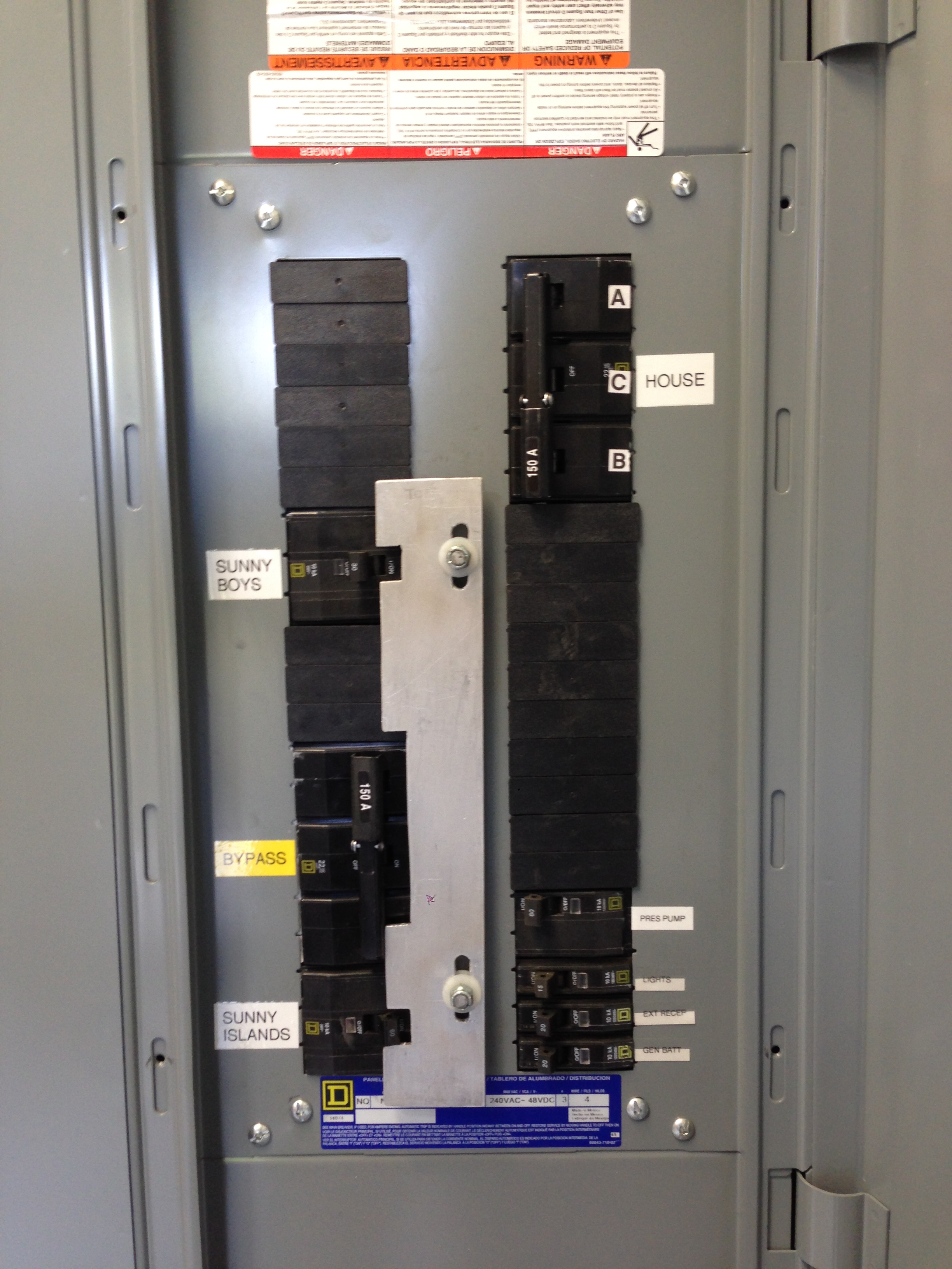
Jason


On Wed, Mar 27, 2024, 6:47 PM Kirk Herander <[email protected]> wrote:

> I agree. That website is way overpriced on their interlocks. I’ve looked
> at the one you made from your photos and it looks good. I guess I’ll have
> to ask you to make me one someday if I am ever in need!!!!
>
> *Kirk Herander / **[email protected] <[email protected]>*
>
> *Owner|Principal, VT Solar, LLC*
>
> *Celebrating our 33st Anniversary 1991-2024!!*
>
> dba Vermont Solar Engineering
>
> 802.559.1225
>
>
> On Wed, Mar 27, 2024 at 5:33 PM William Miller <[email protected]>
> wrote:
>
>> Kirk:
>>
>>
>>
>> Very interesting.  Thank you for that link.
>>
>>
>>
>> Let’s consider the options:
>>
>>
>>
>> ·        The interlocks from this supplier can be a bit pricey ($350-450
>> for what we are talking about).
>>
>>
>>
>> ·        If you want to make your own interlock the materials are less
>> than $10.  The hardest part is cutting clean slots in aluminum plate.  I
>> use a CNC router.  Before I acquired the CNC I made a jig for a standard
>> router.  Or drill, jig saw and file.  The notches are easy to mock up in
>> either CAD format (cardboard or computer) and cut with a band or jig saw.
>> Your first one will take an hour or two to fabricate.
>>
>>
>>
>> ·        Compare this to a Ronk 7416 at about $1500 (I find the Ronks to
>> be a bit wonky to use.  Let’s call them Ronky.)  Add to that the space
>> required and the plumbing and wiring for 400 amps (I think Jason can
>> specify a 200 A switch).  Plus if you are not combining your inverters in
>> an existing load center you need another load center for combining. This
>> can really add up.
>>
>>
>>
>> With either interlock option, the inverter combining, the interlocked
>> bypass and output breakers all fit into one load center.
>>
>>
>>
>> I hope the time we spent on this discussion helps someone out there.
>> That’s why we do it.
>>
>>
>>
>> Wm
>>
>>
>>
>> Miller Solar
>>
>> 17395 Oak Road, Atascadero, CA 93422
>>
>> 805-438-5600
>>
>> www.millersolar.com
>>
>> CA Lic. 773985
>>
>>
>>
>>
>>
>> *From:* Kirk Herander [mailto:[email protected]]
>> *Sent:* Wednesday, March 27, 2024 12:38 PM
>> *To:* RE-wrenches; [email protected]
>> *Cc:* Jason Szumlanski
>> *Subject:* Re: [RE-wrenches] Sol-Ark 15K AC Output
>>
>>
>>
>> www.interlockkit.com - they stock and custom make interlock bypasses
>> including multiple breakers.
>>
>>
>>
>> Square D also makes a 400 A panel which excepts either bolt on or snap on
>> QO breakers.
>>
>>
>>
>>
>>
>>
>>
>>
>>
>>
>> *Kirk Herander / **[email protected] <[email protected]>*
>>
>> *Owner|Principal, VT Solar, LLC*
>>
>> *Celebrating our 33st Anniversary 1991-2024!!*
>>
>> dba Vermont Solar Engineering
>>
>> 802.559.1225
>>
>>
>>
>>
>>
>> On Wed, Mar 27, 2024 at 3:15 PM William Miller via RE-wrenches <
>> [email protected]> wrote:
>>
>> Jason:
>>
>>
>>
>> Replies below.
>>
>>
>>
>> Miller Solar
>>
>> 17395 Oak Road, Atascadero, CA 93422
>>
>> 805-438-5600
>>
>> www.millersolar.com
>>
>> CA Lic. 773985
>>
>>
>>
>>
>>
>> *From:* Jason Szumlanski [mailto:[email protected]]
>> *Sent:* Wednesday, March 27, 2024 3:12 AM
>> *To:* [email protected]
>> *Cc:* RE-wrenches
>> *Subject:* Re: [RE-wrenches] Sol-Ark 15K AC Output
>>
>>
>>
>> William,
>>
>>
>>
>> Thanks for the information on grid peak shaving. That is what I thought
>> could be done. The description is a misnomer of sorts (like a lot of things
>> in Sol-Ark lingo). It's a bit hard to follow and not nearly well
>> enough documented, particularly with respect to parallel systems.  You
>> are welcome.  The Sol-Arc manual is not a great manual in any regards.
>>
>>
>>
>> I follow what you are saying about using the 80A input breakers. The
>> problem I have is that you must set the generator kW to 36,000 in the
>> master inverter, not 9,000W in each inverter. The concept of "underrating"
>> the input breakers theorizes that each inverter will share the generator
>> pass-through equally. I do not know that to be the case. And what happens
>> if the three slave inverters have a fault or are turned off? That would
>> allow the single master to pass through the full generator supply.
>> Obviously this trips the 80A input breaker and protects the conductors, but
>> I feel that is a design deficiency when a single inverter is fully capable
>> of passing through all 150A.  You may be designing for an eventuality
>> that will never occur:  If the inverters fail then they should be repaired
>> or replaced.  While awaiting repair the bypass will keep your loads powered
>> at full capacity.
>>
>>
>>
>> On top of that, I don't think the 80A output breakers are sufficient
>> because each inverter can peak shave 50A with inverter power from the
>> batteries. Add that to the theorized balanced 37.5A "grid" input, and you
>> are at 87.5A of possible throughput.  I am not sure why you are
>> designing to deliver more than the inverters will produce.  The generator
>> support function is intended to assist powering loads when the generator is
>> undersized.  I define that as the generator ampacity being less than that
>> of the inverter system.  The 36kVA generator is greater in ampacity than 4
>> Sol-Arc 15s.  You can turn the generator support function down or off in
>> the Sol-Arc.  I would recommend it be set to off for this project.  (If
>> there are to be occasional loads that are greater than the inverters can
>> deliver, like a welder or a car charger, with the plan I suggested you have
>> a generator-fed panel that can feed those occasional large loads with the
>> generator running.)
>>
>>
>>
>> But assuming the 80A input/output concept works, other than a panelboard
>> with bolt on breakers, what low-cost load center allows you to fasten four
>> 80A backfed breakers? If this is available, I could use a recommendation.
>> The load centers I am familiar with only have provisions for one fastened
>> backfed breaker.  I use to specify bolt-on panels for this but I came to
>> believe this is overkill.  QO breakers are held in place by the panel cover
>> that overlaps the breakers.  Other breakers are configured so the contact
>> points for the breaker bus are recessed.  You need to convince your AHJ
>> that this satisfies the requirement.  Part of the discussion should include
>> the point that off-grid systems are specialized and people that do not
>> understand them should not be working on them (or judging them-- is what I
>> tell inexperienced plan-checkers).
>>
>>
>>
>> With respect to the bypass, I would usually use a DPDT switch to
>> accomplish this, Even for 400A bypasses, there seems to be a relatively
>> cost effective option in the Ronk 7416 (which to date I have not used). I
>> get the concept for smaller (<=100A) generators that you could use a
>> generator interlock on an off-the-shelf load center. But they typically
>> only allow a single backfed 2-pole breaker, whereas something like a Square
>> D QO panel with a backfed 150A breaker requires 4 spaces and is
>> incompatible with the interlock device.  Since bypass is an emergency
>> condition, I sometimes limit my bypass to 100 amps.  If you want full
>> bypass ampacity you can build an interlock to accommodate any size
>> breaker.  Here
>> <https://millersolar.com/MillerSolar/Portfolio/Commercial/RM/Interlock.JPG>
>> is a photo of a large frame breaker being interlocked.  Here
>> <https://millersolar.com/MillerSolar/Portfolio/Commercial/RM/RM_Interlock.pdf>
>> is a design sketch exploring multiple interlock options.
>>
>>
>>
>> Always, this is a great discussion and specific recommended equipment is
>> appreciated.
>>
>>
>> Jason Szumlanski
>>
>> Principal Solar Designer | Florida Solar Design Group
>> NABCEP Certified Solar Professional (PVIP)
>> Florida State Certified Solar Contractor CVC56956
>>
>> Florida Certified Electrical Contractor EC13013208
>>
>>
>>
>>
>>
>> On Wed, Mar 27, 2024 at 12:33 AM William Miller <[email protected]>
>> wrote:
>>
>> Jason:
>>
>>
>>
>> Sol-Arc does provide generator support.  They call it “grid peak load
>> shaving” and it is described on page 22 of the manual.  Below is an excerpt.
>>
>>
>>
>> *Error! Filename not specified.*
>>
>>
>>
>> For those that may not be familiar with the concept of generator support,
>> here is how I describe it:  The inverter(s) are programmed for the
>> generator capacity.  If the generator is powering loads and the demand
>> exceeds that programmed generator capacity, the inverter can start
>> inverting and synchronize output to the generator to add power.  This is
>> only possible if battery charge levels are adequate.  In the Sol-Arc this
>> function can be adjusted or turned off.
>>
>>
>>
>> Regarding my recommendations on wire sizing:  I may have done a poor job
>> describing how I see your project best approached.  Below is a diagram that
>> may do a better job.  Power flow is from left to right:
>>
>>
>>
>> *Error! Filename not specified.*
>>
>>
>>
>> If you follow what I am laying down, you can see there is no single
>> inverter or inverter wire that can pass or create more than 80 amps.  Ergo
>> #4 copper.  The money and time you save can easily purchase 8 80 amp
>> breakers.  If you look at Diagram 10 in the April 5, 2022 Sol-Arc manual
>> you will see this concept shown, albeit without bypass capabilities and
>> with a separate “LOAD AC Combiner panel.”  The separate panel is
>> redundant,-- all of the breakers in the AC combiner panel could be located
>> in the “Main Breaker Panel.”
>>
>>
>>
>> Contemplate this:  Just because an inverter can pass-through 200 amps,
>> does not mean it can pass through amps above what the input breaker
>> provides.
>>
>>
>>
>> I hope I have been more clear.  I also hope you don’t spend a lot of
>> money on and wrassle wire larger than is needed.
>>
>>
>>
>> Call me if I can help in any way.
>>
>>
>>
>> William
>>
>>
>>
>> PS:  Below is a diagram on how to provide bypass.  I tried to depict the
>> bypass interlock graphically.  The point is you cannot turn *on* the
>> bypass breaker without turning *off* the inverter output breakers.  See
>> photos of the actual hardware on the web page linked below.  I find bypass
>> very handy because if there is an inverter or battery failure the client
>> can restore power immediately and I can respond at a more convenient time.
>>
>>
>>
>>
>>
>> *Error! Filename not specified.*
>>
>>
>>
>>
>>
>> Wm
>>
>>
>>
>> Miller Solar
>>
>> 17395 Oak Road, Atascadero, CA 93422
>>
>> 805-438-5600
>>
>> www.millersolar.com
>> <https://mailtrack.io/l/3deb3f7f51095bae3cfd8b42df221b4dca044e0a?url=http%3A%2F%2Fwww.millersolar.com%2F&u=1613865&signature=79e9e2e0e8d662d0>
>>
>> CA Lic. 773985
>>
>>
>>
>>
>>
>> *From:* Jason Szumlanski [mailto:[email protected]]
>> *Sent:* Tuesday, March 26, 2024 6:41 PM
>> *To:* William Miller; RE-wrenches
>> *Subject:* Re: [RE-wrenches] Sol-Ark 15K AC Output
>>
>>
>>
>> #4 wire as the output of each inverter is definitely not adequate, as
>> each inverter can pass through 150A of generator power. In theory it would
>> be spit across all four, but that doesn't matter. It's an open spigot, so
>> at a minimum the output conductors would need to be 150A rated in my
>> opinion. The complication arises when you don't know whether the inverter
>> can supplement this AC output all the way to the 200A load OCPD integral to
>> the inverter. For that reason, I believe you need to size the output
>> conductors to 200A, not 150A in this case. I am trying to find out
>> definitively if generator support mode is supplied by Sol-Ark s.
>>
>>
>>
>> As for paralleling the outputs, landing the outputs on breakers becomes
>> problematic and very expensive. Since the outputs need to be 150A minimum
>> or 200A maximum (as discussed previously), how would you do a 400A
>> panelboard with four of these large breakers in it, keeping in mind that
>> all four need to be fastened as backfed main breakers? I don't see a
>> practical way to make that happen.
>>
>>
>>
>> The same thing applies to combining the generator inputs. You would need
>> 4 x 150A backfed breakers, all fastened to the bus. Is there a cost
>> effective way to accomplish this?
>>
>>
>>
>> Serviceability and bypass are obvious desires, but at what cost? If an
>> inverter needs to be taken out of service, it's fairly easy to remove the
>> supply and load conductors. And this highlights my issue... What if three
>> of four inverters need to be removed from service? Then absolute 150A
>> generator power can flow through the remaining single inverter, meaning the
>> output conductors need to be sized accordingly.
>>
>>
>>
>> Jason
>>
>>
>>
>>
>>
>> On Tue, Mar 26, 2024, 9:15 PM William Miller via RE-wrenches <
>> [email protected]> wrote:
>>
>> Jason:
>>
>>
>>
>> I am wondering on the advisability of hardwiring the outputs of all four
>> inverters together.  If one inverter fails the other three can backfeed
>> into it without any means to disconnect the failed inverter and without
>> over-current protection.  Have you considered landing the output of each
>> inverter on a separate, appropriately sized 2 pole breaker in the output
>> load-center?
>>
>>
>>
>> In the same vein, how are you feeding generator input into the
>> inverters?  Are these hard-wired paralleled as well?  You might consider
>> having the generator feed a dedicated load-center with an appropriately
>> sized breaker to feed each inverter.  You protect the conductors as
>> required and you can isolate any inverter for service
>>
>>
>>
>> What size should these breaker be?  If your inverter can supply 62.5 AAC,
>> upsizing for continuous duty and to the next higher standard breaker size
>> you get 80 amps.  If you use 80 amp breakers into and out of each Sol-Arc
>> you require #4 copper at 75°C.  Each inverter and all of the conductors are
>> protected for the max current they will see and you get the combined
>> amperage at your output.  There should be no need to run 400 amp wire.
>>
>>
>>
>> BTW, you can easily contrive a bypass system by creating a sliding
>> mechanical interlock.  You run an appropriately sized feeder between the
>> generator fed and inverter fed panels.  The bypass breaker in the
>> inverter-fed panels is interlocked with the inverter output breakers.  The
>> installation might look like this
>> <https://mailtrack.io/l/e90ccdb6d87171ee02747bc52f4aa4c7f57064ca?url=https%3A%2F%2Fmillersolar.com%2FMillerSolar%2FPortfolio%2FInverters%2Fbattery_iinverters%2FChimney_Rock%2FChimney_rock.html&u=1613865&signature=38c4488f52bdc385>.
>> This is way cheaper and easier than installing an additional 200A,
>> double-throw safety switch.  (A home-made interlock may not be listed but
>> what is the worse that will happen if all breakers are on?  The inverters
>> will detect backfeed and shut down.  No harm will come of it.)
>>
>>
>>
>> Hope this helps.
>>
>>
>>
>> William
>>
>>
>>
>> Miller Solar
>>
>> 17395 Oak Road, Atascadero, CA 93422
>>
>> 805-438-5600
>>
>> www.millersolar.com
>> <https://mailtrack.io/l/7e13e4b3b56e5496552a9f21904f404635490f63?url=http%3A%2F%2Fwww.millersolar.com%2F&u=1613865&signature=6c634bcc39faeca3>
>>
>> CA Lic. 773985
>>
>>
>>
>>
>>
>> *From:* RE-wrenches [mailto:[email protected]] *On
>> Behalf Of *Jason Szumlanski via RE-wrenches
>> *Sent:* Tuesday, March 26, 2024 2:26 PM
>> *To:* RE-wrenches
>> *Cc:* Jason Szumlanski
>> *Subject:* [RE-wrenches] Sol-Ark 15K AC Output
>>
>>
>>
>> I am going to have a quad-stack of Sol-Ark 15K for an off-grid 120/240V
>> system with a 150A generator. I know the max real power is 62.5A each
>> inverter including battery and PV. That would be 62.5A x 4 = 250A total. I
>> intend to connect the output of the 4 inverters together with a 5-port
>> Polaris tap, with the output of the Polaris Tap going to a 400A main lug
>> only panelboard.
>>
>>
>>
>> My question revolves around the 200A passthrough capability for the
>> generator, which is 150A max output and would be connected to the Grid
>> input on each inverter. Since each inverter would need to handle the full
>> pass-through current, that would require minimum 150A conductors on the
>> input side of each inverter. I am under the impression that the inverters
>> can supplement the "grid" or generator in this case if the current exceeds
>> the available input. That means the inverter would have 150A of input plus
>> 62.5A  of inverter power for a total of 212.5A. But there is a 200A load
>> OCPD, so I could size the load conductors from each inverter for 200A.
>>
>>
>>
>> Obviously the 4 inverters can only pass through 150A from the generator
>> in total, which would probably be split among them, but could go through a
>> single unit if the rest fail.
>>
>>
>>
>> Now, is it possible for each inverter to output 62.5A each PLUS 150A of
>> generator power spread across them for a total of 400A? That is important
>> because I would need to size the combined output conductors for 400A if
>> that is the case.
>>
>>
>>
>> I guess I'm not clear on how Sol-Ark 15K handles grid/generator
>> assist/supplement. It does not seem to be documented clearly.
>>
>>
>>
>> Jason Szumlanski
>>
>> Florida Solar Design Group
>>
>>
>>
>>
>>
>> _______________________________________________
>> List sponsored by Redwood Alliance
>>
>> Pay optional member dues here: http://re-wrenches.org
>> <https://mailtrack.io/l/5f5ecb45fa0ccb0d11cccafb2c0f97618fa79e70?url=http%3A%2F%2Fre-wrenches.org&u=1613865&signature=fdeabe6cf92ab25a>
>>
>> List Address: [email protected]
>>
>> Change listserver email address & settings:
>> http://lists.re-wrenches.org/options.cgi/re-wrenches-re-wrenches.org
>> <https://mailtrack.io/l/020c93287659704ad1c52093f304e341f5d0498c?url=http%3A%2F%2Flists.re-wrenches.org%2Foptions.cgi%2Fre-wrenches-re-wrenches.org&u=1613865&signature=3efe2a50c80c33a7>
>>
>> There are two list archives for searching. When one doesn't work, try the
>> other:
>> https://www.mail-archive.com/[email protected]/
>> <https://mailtrack.io/l/52cc42ac082af0eeca614dbe4c0d638d5d336ad1?url=https%3A%2F%2Fwww.mail-archive.com%2Fre-wrenches%40lists.re-wrenches.org%2F&u=1613865&signature=209030a25db2ff5a>
>> http://lists.re-wrenches.org/pipermail/re-wrenches-re-wrenches.org
>> <https://mailtrack.io/l/f48fe27d75d453c7157b484946d36bcdf4698ad0?url=http%3A%2F%2Flists.re-wrenches.org%2Fpipermail%2Fre-wrenches-re-wrenches.org&u=1613865&signature=42f5213a717423ce>
>>
>> List rules & etiquette:
>> http://www.re-wrenches.org/etiquette.htm
>> <https://mailtrack.io/l/076ca2ee1c125ea468d20fa3e4c460f58b568b0d?url=http%3A%2F%2Fwww.re-wrenches.org%2Fetiquette.htm&u=1613865&signature=96238382e5fb3b50>
>>
>> Check out or update participant bios:
>> http://www.members.re-wrenches.org
>> <https://mailtrack.io/l/d6a9b62f894eaeef0e7d7d91724b427d785ae85e?url=http%3A%2F%2Fwww.members.re-wrenches.org&u=1613865&signature=e4238f11cf07c6fa>
>>
>> _______________________________________________
>> List sponsored by Redwood Alliance
>>
>> Pay optional member dues here: http://re-wrenches.org
>>
>> List Address: [email protected]
>>
>> Change listserver email address & settings:
>> http://lists.re-wrenches.org/options.cgi/re-wrenches-re-wrenches.org
>>
>> There are two list archives for searching. When one doesn't work, try the
>> other:
>> https://www.mail-archive.com/[email protected]/
>> http://lists.re-wrenches.org/pipermail/re-wrenches-re-wrenches.org
>>
>> List rules & etiquette:
>> http://www.re-wrenches.org/etiquette.htm
>>
>> Check out or update participant bios:
>> http://www.members.re-wrenches.org
>>
>>
_______________________________________________
List sponsored by Redwood Alliance

Pay optional member dues here: http://re-wrenches.org

List Address: [email protected]

Change listserver email address & settings:
http://lists.re-wrenches.org/options.cgi/re-wrenches-re-wrenches.org

There are two list archives for searching. When one doesn't work, try the other:
https://www.mail-archive.com/[email protected]/
http://lists.re-wrenches.org/pipermail/re-wrenches-re-wrenches.org

List rules & etiquette:
http://www.re-wrenches.org/etiquette.htm

Check out or update participant bios:
http://www.members.re-wrenches.org