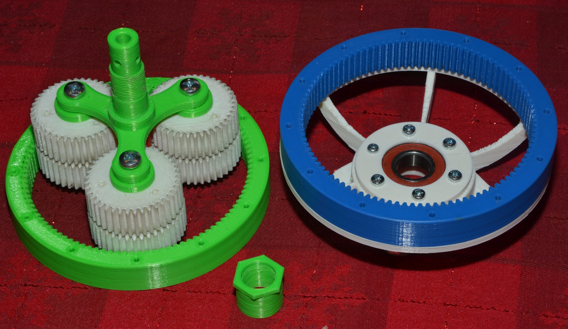
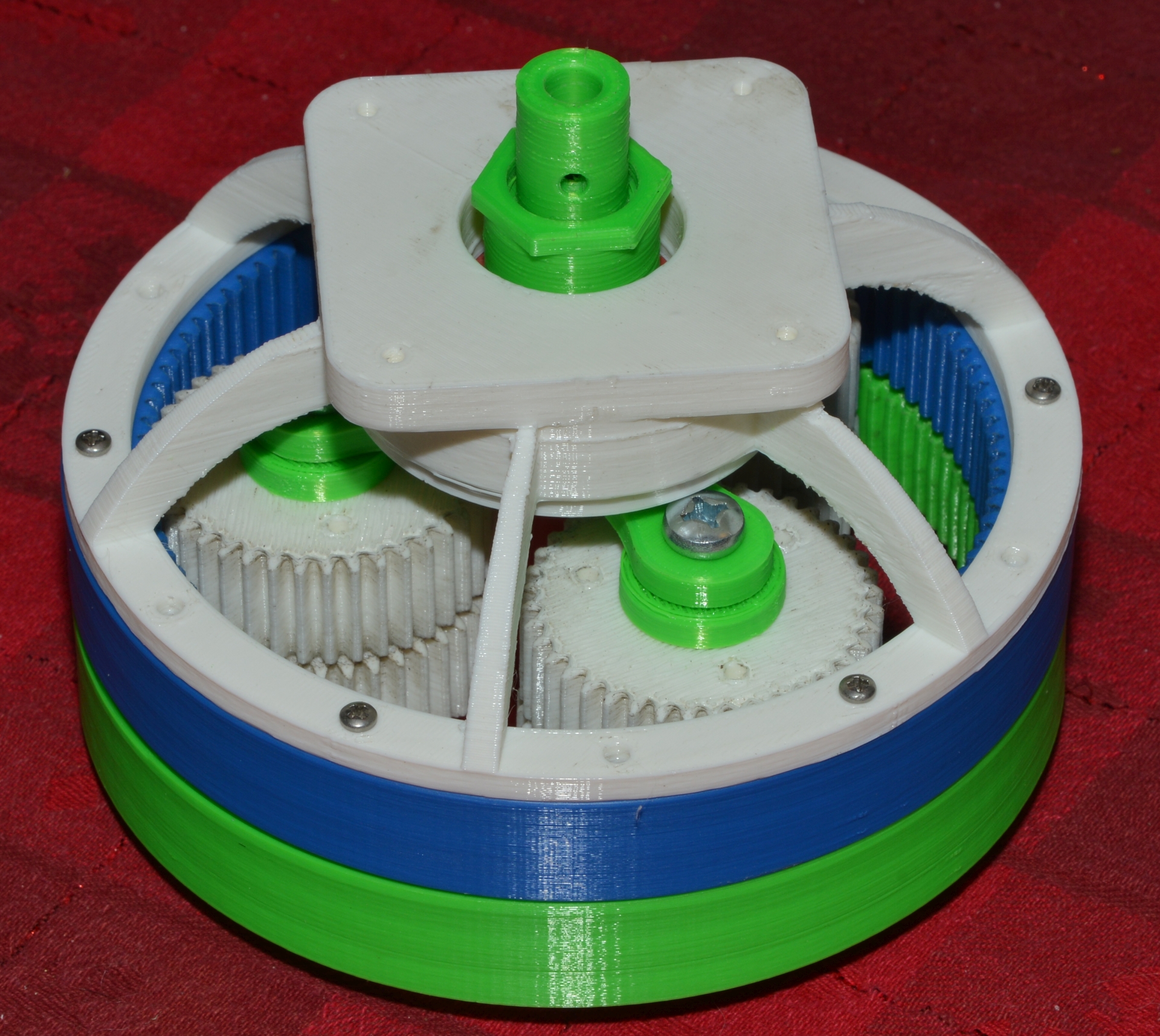
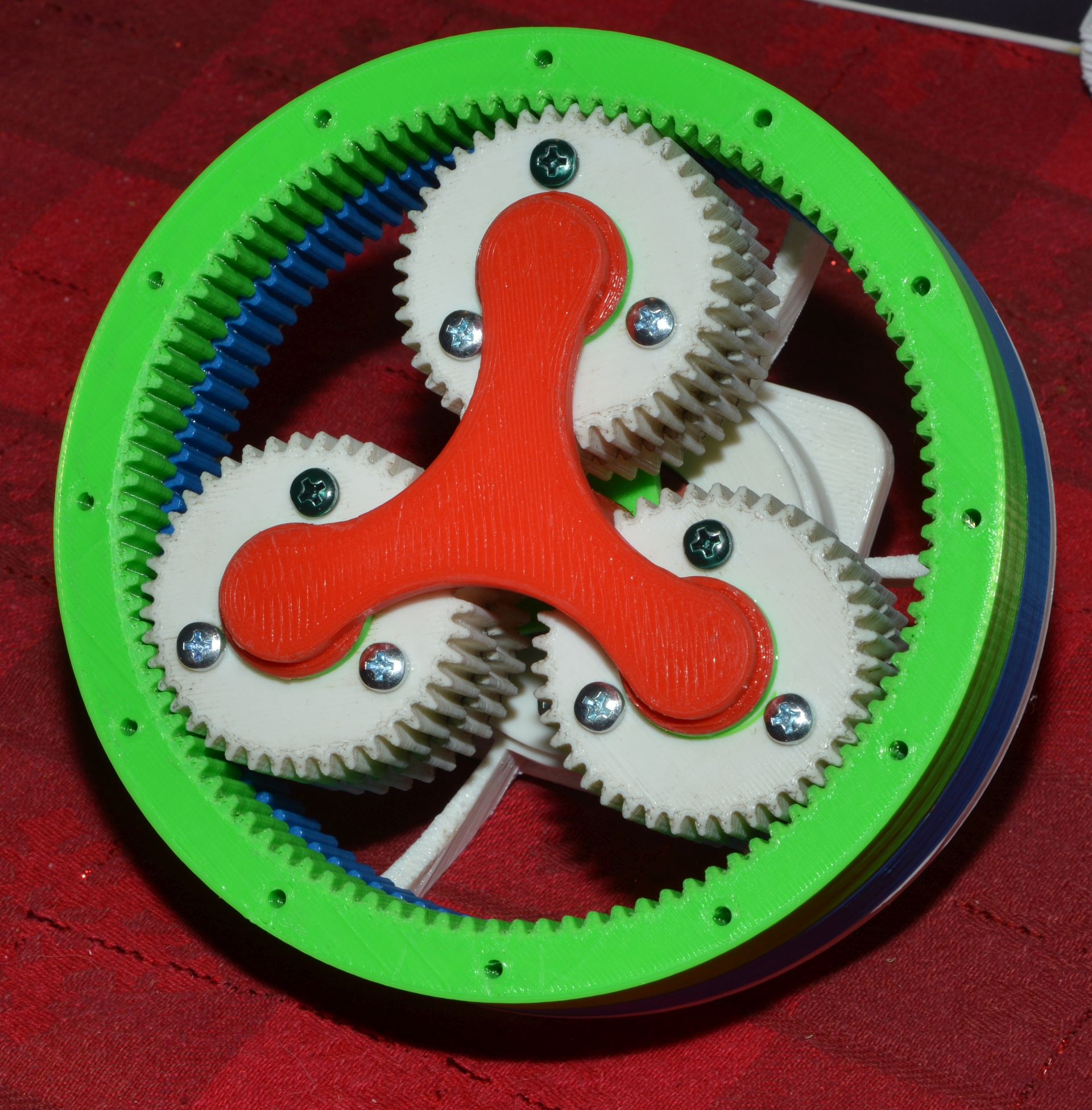
Small progress report on Todd's version of the harmonic drive.

I added a back mount that holds a 19x40x12 bearing.  A cap to hold the bearing
in place.   Then a new drive arm sized to 19mm and a 19x1.25mm thread along
with a nut.  The end of the drive shaft has an 8mm hole for the stepper motors
that arrived last week.  Will likely require a metal collar around that part
with threaded holes to clamp the flats on the motor shaft.  The plastic just
isn't strong enough to hold these types of threads.
http://www.autoartisans.com/harmonicdrive/BearingDriveShaft-1.jpg
http://www.autoartisans.com/harmonicdrive/BearingDriveShaft-2.jpg
http://www.autoartisans.com/harmonicdrive/BearingDriveShaft-3.jpg

Now to contain the green output gear.  Here's one idea.  I have a bag of 5.5mm
steel balls meant for keeping model paint mixed.  With 80 of them held in place
by the bearing spacer (which I would probably make out of metal for this
project) it should theoretically capture the gear and reference it to the
mounted frame.  A dual row of balls might be better.

http://www.autoartisans.com/harmonicdrive/BearingPath.jpg
http://www.autoartisans.com/harmonicdrive/BearingSpacer.jpg
http://www.autoartisans.com/harmonicdrive/MountFrame.jpg

Commercial units look like they use rollers set at angles but even a 32mm one
from aliexpress is over $200.

Probably the next best step to create something like this is to down size it to
brass or steel gears small enough to fit into a much lower cost set of
bearings.   The key with this system will be the bearings.

Anyway, other than printing a conversion base for motor to bearing assembly I'm
not sure this warrants further work unless I can come up with an inexpensive
method to contain the front gear.  Suggestions, as always are welcome.

John


_______________________________________________
Emc-users mailing list
Emc-users@lists.sourceforge.net
https://lists.sourceforge.net/lists/listinfo/emc-users