On 03/10/2011 11:41 PM, Robert LaJeunesse wrote:
Poor man's solution: Use an Arduino to read the Thunderbolt 1PPS and lock a 50Hz
(or 60Hz) square wave to the 1PPS. Any resulting jitter can likely be kept in
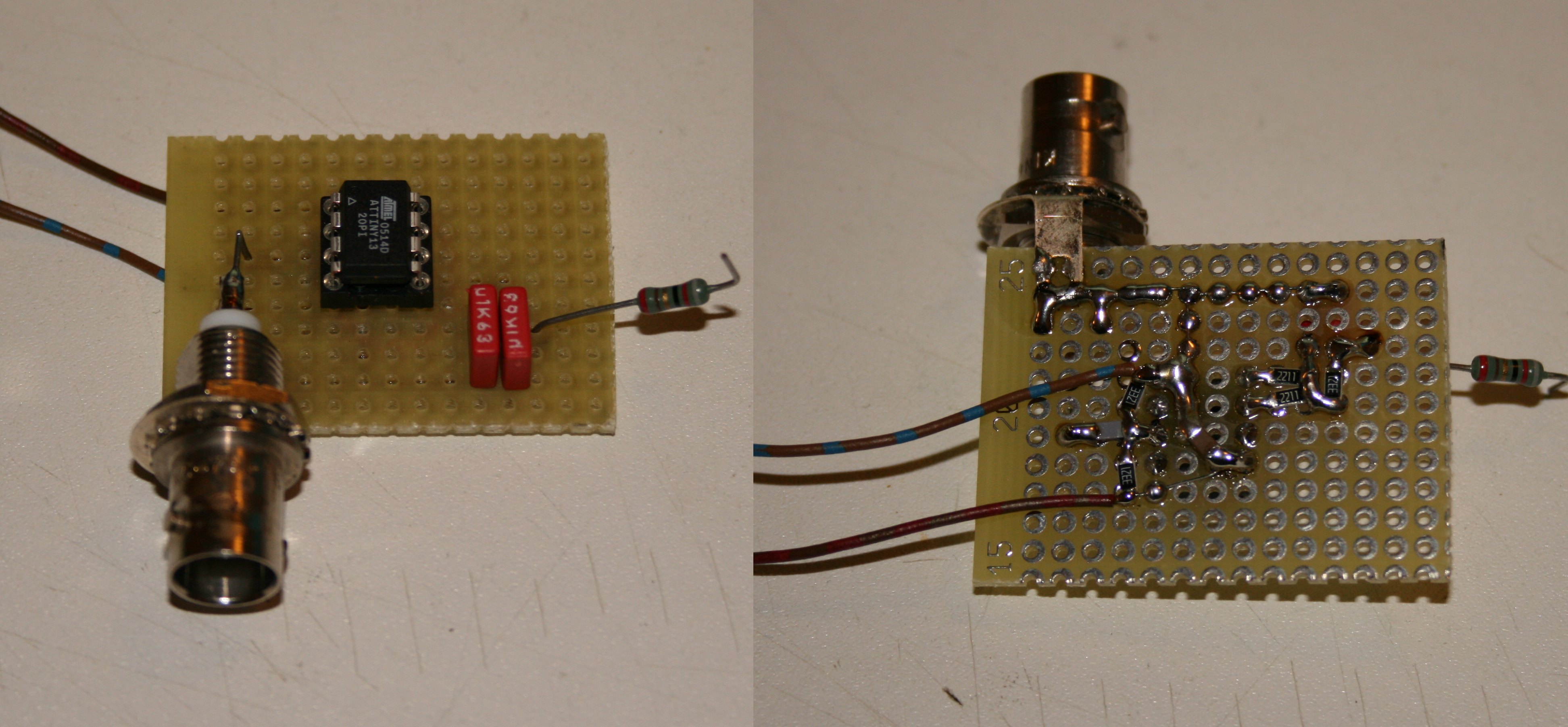
Here is an even poorer man's solution (and plug):
A DDS using both compare outputs of an 8 pin part to get
a phase-centered PWM with half the usual ripple.
With PPS input as a bonus so the zero crossing occurs where
you want it to.

http://n1.taur.dk/gen60a.jpg

Output 5Vpp@60Hz +1.1mVpp@39kHz. Very pretty sinewave.


//
  TinyAWG.c
//  60Hz generator - 2011 Kasper Pedersen - Beerware license
//
//  This is an arbirtrary waveform generator set up to produce 60Hz sine
//  Compile with GCC -Os
//
//
// 2-5V  -------+-----------------------------+
//              |                             |
//              |        ______________       |
//              |     __|*             |__    |
//             | |   |__|          VCC |__|---+--||--+
//           3k| |      |              |         1u  |
//              |     __|              |_           _|_
// 10MHz ---||--+----|__| CLK      LOCK|__|         GND
//         1n   |       |              |
//             | |    __|              |__    ___      ___
//           3k| |   |__| PPS      PWM1|__|---___--+---___-------+
//              |       |              |      2k2  |   3k3       |
//              |     __|              |__    ___  |             |
// GND   -------+----|__| GND      PWM0|__|---___--+--||--+--||--+---------
//              |       |______________|      2k2    100n |  100n
//              |          ATTINY13V                      |        60Hz out
//              |                                         |
//              +-----------------------------------------+----------------
//
//
//  Rising edge on PPS input (optional) will steer the output
//  so that, after 128 edges, the positive zero crossing
//  of the output will coincide with PPS.
//  When this happens, LOCK will go high.
//
//  PWM frequency is 39kHz
//  first filter stage attenuates 27x
//  second filter stage attenuates 81x and pulls phase 1 deg.

#include<avr/io.h>
#include<avr/interrupt.h>
#include<avr/pgmspace.h>

#define DCBIAS 127
PROGMEM unsigned char table[256]={
 127,130,133,136,139,142,145,149,152,155,158,161,164,167,169,172,
 175,178,181,184,186,189,192,194,197,200,202,205,207,209,212,214,
 216,218,220,222,224,226,228,230,232,233,235,237,238,240,241,242,
 243,245,246,247,248,248,249,250,251,251,252,252,252,253,253,253,
 253,253,253,253,252,252,252,251,251,250,249,248,248,247,246,245,
 243,242,241,240,238,237,235,233,232,230,228,226,224,222,220,218,
 216,214,212,209,207,205,202,200,197,194,192,189,186,184,181,178,
 175,172,169,167,164,161,158,155,152,149,145,142,139,136,133,130,
 127,124,121,118,115,112,109,105,102,99,96,93,90,87,85,82,
 79,76,73,70,68,65,62,60,57,54,52,49,47,45,42,40,
 38,36,34,32,30,28,26,24,22,21,19,17,16,14,13,12,
 11,9,8,7,6,6,5,4,3,3,2,2,2,1,1,1,
 1,1,1,1,2,2,2,3,3,4,5,6,6,7,8,9,
 11,12,13,14,16,17,19,21,22,24,26,28,30,32,34,36,
 38,40,42,45,47,49,52,54,57,60,62,65,68,70,73,76,
 79,82,85,87,90,93,96,99,102,105,109,112,115,118,121,124};

unsigned char phase;
signed acc;
unsigned char lastp=1;

ISR(SIG_OVERFLOW0)
{
        signed s;
        unsigned char v;
        //60Hz*256=15360Hz increment rate.
        //irq rate is 10MHz/256=39062.5Hz.
        //we need to increment at: 60*256*256 / 10M
        //split into primes and eliminate common factors:
        //10MHz       = 2^7 *     5* 5^6
        //60*256 *256 = 2^7 *2 *  5 *2*2*3 * 2^8
        //scaler = 2*2*2*3*256  / 5*5*5*5*5*5
        //       = 6144 / 15625

        v=__LPM(&table[phase]); //generate output
        OCR0A=v;
        OCR0B=(2*DCBIAS)-v;

        s=acc; //generate phase
        s-=6144;
        if (s<0) {
                acc= s+15625;
                ++phase;
        } else {
                acc= s;
        }

        if (PINB&16) { //on rising edge: adjust phase so this conincides with
the positive zero crossing.
                if (!lastp) { //we need 128 pulses to become adjusted
                        lastp=1;
                        if (!phase) {
                                //phase is 0. At 15kHz we are within 65us
                                PORTB|=4;
                        } else
                        if (phase&0x80) {
                                ++phase; // 65us adjustments
                                PORTB&=~4;
                        } else {
                                --phase;
                                PORTB&=~4;
                        }
                }
        } else {
                lastp=0;
        }
}

void main(void)
{
        TCCR0A=0xB3; //A is clear on match, positive output when bigger
        TCCR0B=0x01;
        TIMSK0=0x02;
        DDRB|=1;  //output
        DDRB|=2;
        DDRB|=4;   //"locked" output
        PORTB|=16; //~50uA pullup on PPS pin.
        sei();
        for (;;);
}


_______________________________________________
time-nuts mailing list -- [email protected]
To unsubscribe, go to https://www.febo.com/cgi-bin/mailman/listinfo/time-nuts
and follow the instructions there.