Thanks Arthur. Thats the thread I was referring to.

On Tue, Jan 31, 2012 at 10:25 AM, Arthur Dent <[email protected]>wrote:
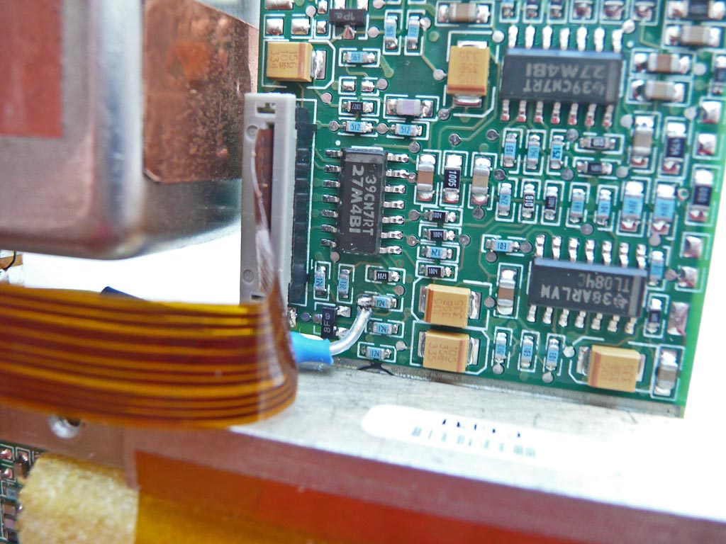
> >Tue Jan 31 14:15:57 UTC 2012
> >I did the mod and getting to pin 5 was tough. However Doug mentioned that
> >there is another point to the left of the chip thats easier to get to.
> >Don't recall the point. But if the lead ever comes off of 5 I can assure
> >you I will find it. :-)
> >My unit zeroed about at about 2 V. So I am using a 10 T 10 K bourns pot
> >with 1000 counter. Then a 3.3V reg directly attached with bypass caps
> >driven by 8 V from the regulated supply in the RB.
> >Very clean, 3 leads into the RB. Using shielded cable through the pot hole
> >that actually does nothing.
> >Regards
> >Paul.
> +++++++++++++++++++++++++++++++
>
> In case you missed it I had posted the information and a photo of the spot
> to more easily solder the 100K resistor to give you EFC. I'd go with Bill
> Riches'
> suggestion to have the 100K in series with the EFC line. I connected the
> lead
> from the 100K to a pin on the DB-9 connector that was freed up when I put
> the
> 5V regulator inside so I could run off a single supply. Here's what I did.
>
> +++++++++++++++++++++++++++++++
> >Sun Jan 15 18:31:39 UTC 2012
> >I didn't solder the resistor directly to pin 5 of the IC. I found that
> pin 5
> >was connected to a nearby SMD capacitor that was a little easier to
> >solder to. Attached is a photo of the correct location if you want to try
> >bringing the EFC out for analog control.
> > http://farm8.staticflickr.com/7170/6702435071_f684967719_b.jpg
>
>
> >Mon Jan 16 04:16:53 UTC 2012
> >I'm not sure what HEX number was loaded into my 5680A but the frequency
> >was just slightly off from 10Mhz. Pin 5 on my 27M4BI quad opamp 'floats"
> at
> >2.599V and to get 10Mhz out it needs to be at 2.445V. I guess I could
> correct
> >the frequency digitally so it is at 10Mhz with pin 5 floating but I don't
> feel it is
> >necessary. The output frequency I measured with zero volts on pin 5
> (through
> >the 100K resistor) was 10,000,000.028Hz  and with 5V it was pretty close
> to
> >9,999,999.969Hz or .031Hz low so it's close to centered. I tried using a
> 2K
> >10-turn pot with about 10K on each side to restrict the tuning range
> further and
> >give me finer control. After the 5680A had been on for a while I tried
> setting
> >the frequency  as close to 10Mhz as I could and watch the drift on my
> scope
> >using the 10Mhz Rb from my Datum 9390 GPS receiver as the reference.
> >The 5680A seemed to stay within 5ns for 45 minutes so the resolution on
> the pot
> >is quite good  and the 5680A seems quite stable.
> >
> >The pin 5 IC connection is the non-inverting input to the opamp and I'm
> not
> >sure if connecting the 100K resistor to the inverting input, pin 6, would
> give
> >you a positive change in frequency for a positive change in voltage or
> not.
> >If you're using a pot for adjustment or if the controller can be
> programmed
> >to change the polarity, it doesn't really make any difference and pin 5
> works
> >just great. I'm glad Bill Riches found this input and posted the
> information.
>
> -Arthur
> _______________________________________________
> time-nuts mailing list -- [email protected]
> To unsubscribe, go to
> https://www.febo.com/cgi-bin/mailman/listinfo/time-nuts
> and follow the instructions there.
>
_______________________________________________
time-nuts mailing list -- [email protected]
To unsubscribe, go to https://www.febo.com/cgi-bin/mailman/listinfo/time-nuts
and follow the instructions there.