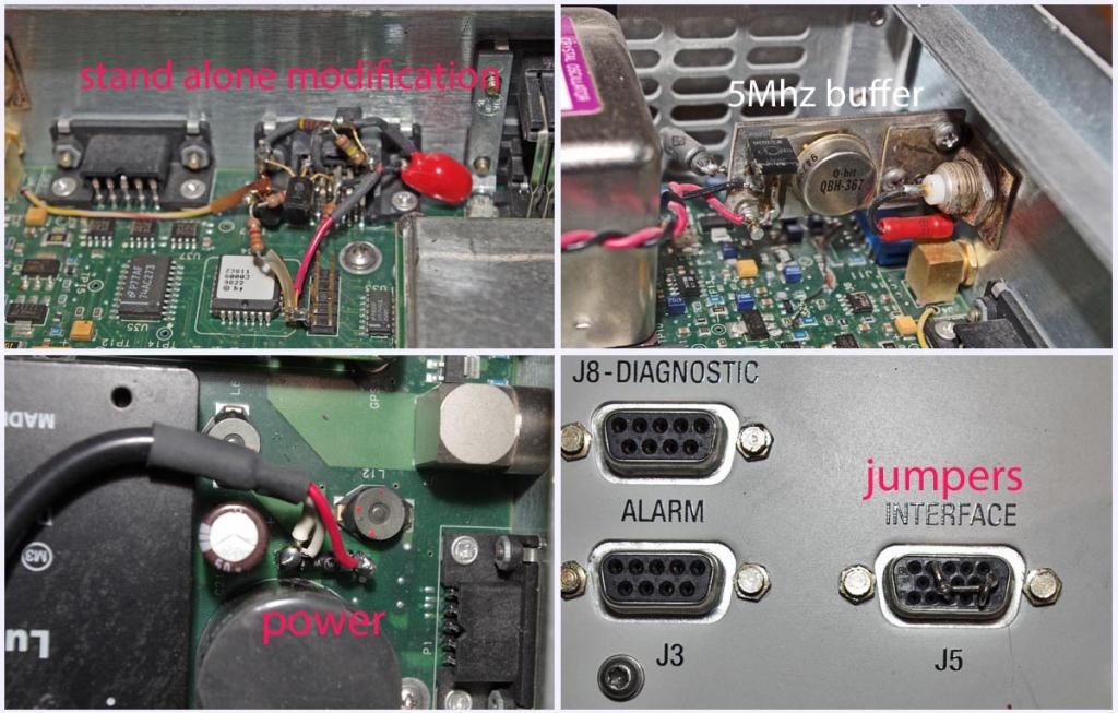
Keep in mind that I made the modifications to my RFTG-u REF 1 almost
4 years ago and the details of why I did what I did are kind of foggy
today. It was a pure hack but I *believe* that the circuitry as well
as the jumpers were required, or at least I thought so. The big problem
with getting something like this to work is that after spending a lot
of time on it I generally go on to the next project and as long as what
I did works, I forget about it because it is a one of a kind thing. The
photo link below shows the 5Mhz buffer amp I connected to the TP in
front of the oscillator that uses a mounting bracket that is secured
by the BNC connector that outputs the 5Mhz. The 24V/2A power supply that
I mounted on the back connects across the diode on the circuit board as
shown. The transistors and other components of the modification that are
mounted free form on the back of the J5 connector get the +5VDC from
the header directly in back of J5. The wire on the left goes through an
existing hole on the circuit board to connect to the fault LED.
I was hoping that someone else would duplicate the modification just to
reassure me that what I did wasn't black magic. It looks like Nigel is
doing just that-thanks.


http://i906.photobucket.com/albums/ac262/rjb1998/RFTG-uREF1_zps546e4c82.jpg
_______________________________________________
time-nuts mailing list -- [email protected]
To unsubscribe, go to https://www.febo.com/cgi-bin/mailman/listinfo/time-nuts
and follow the instructions there.