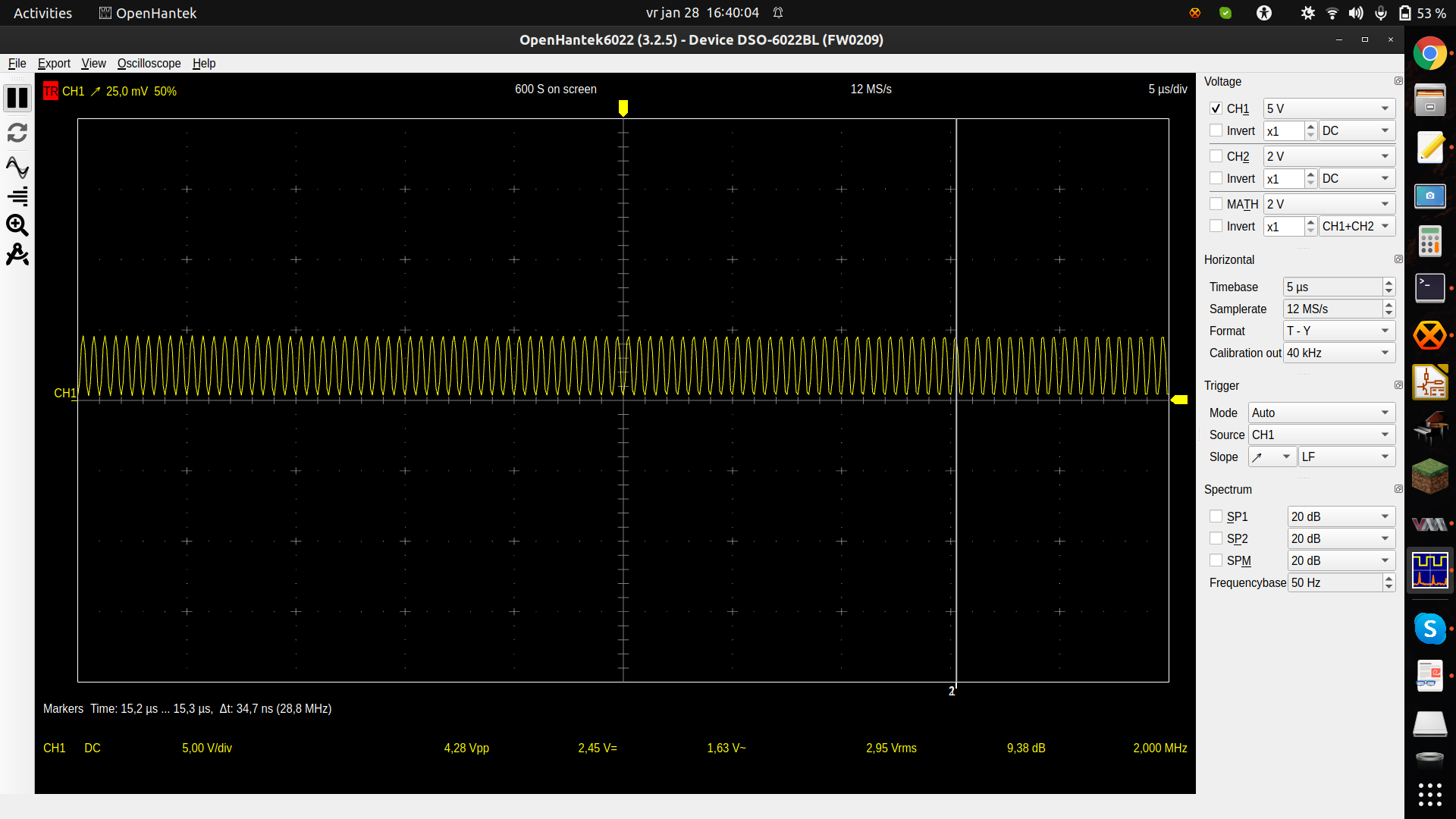
On Fri, January 28, 2022 1:41 pm, folkert wrote:

> Now I bought a "Square Wave Amplifier" by BG7TBL (
> https://www.aliexpress.com/item/4000192799858.html?gatewayAdapt=glo2nld&spm=a2g0o.9042311.0.0.3d764c4dMZPAX8
> ). Documentation I could find was a bit vague about the
> output voltage but I measured 5v with a scope (see
The listing on aliexpress says pretty clearly 5v p-p output square wave.
It does not specify the output impedance, but likely 50 Ohm.

> https://vanheusden.com/permshare/scope.png - the scope software says
> 2MHz but output is really 10MHz).

I don't see on the scope display any indication of the input impedance.
Does your scope have the traditional ability to switch between 1M Ohm
input and 50 Ohm input.
If your scope was set for 1M Ohm input, try setting it to 50 Ohm and check
again.  If the buffer amplifier has 50 Ohm output impedance, then the
amplitude should drop to 2.5V when the scope is set to 50 Ohm input. If
the amplitude stays close to 5V then it has low impedance output, which
will be relevant for how you terminate your long coax cables.

> The 50 ohm bnc cable between
>   the amplifier and the rpi is 3m long.

That is long enough that for fast rise time square waves you should
terminate in the characteristic impedance of the cable (50 Ohms).  You can
have either series 50 Ohms at the sending end, parallel 50 Ohms at the
receiving end, or both.  You need to determine whether the amplifier
already has 50 Ohm output impedance to know whether doing both is even an
option.

The physics has to do with conservation of energy, but the very short
version is that if the impedance of the sending and receiving devices do
not match, you can get reflections of the signal traveling back and forth
along the cable.
Going into an explanation of transmission line theory is more than I have
time for in this email, but you should be able to find much information
online by searching for "transmission line" and "transmission line
termination."

> - or should I use a voltage divider? I was thinking of a 4.7k ohm and
>   8.2k ohm resistor giving slightly less than 3.2v - will that work? or
>   will that attenuate the signal too much?

As pointed out previously the resistance forms a RC low pass filter with
the capacitance of the device package (not a separate device on the board,
just a capacitance effect from the physics of packaging an integrated
circuit), so lower resistance may work better, assuming you want to keep
the faster edge rate.

> - can I feed the picdiv 5v on its GPIO pin while giving it a 3.3v
>   voltage so that it outputs 3.3v as well to the rpi pins?

The datasheet for the PIC12F675 says absolute maximum input voltage on the
pins is VDD + 0.3V, so no, you should not use a 5V signal when running
from 3.3V.   You could power the PICDIV from 5V, and divide down at the
output of the PIC rather than the input.
But you may not need to, depending on the result of your experiment with
50 Ohm scope input impedance.

--
Chris Caudle

_______________________________________________
time-nuts mailing list -- [email protected] -- To unsubscribe send an
email to [email protected]
To unsubscribe, go to and follow the instructions there.