ب.   بببببببب0ببب
-----Original Message-----
From: [email protected]
Sender: [email protected]
Date: Sun, 23 Jan 2011 12:00:03
To: <[email protected]>
Reply-To: [email protected]
Subject: Tinyos-help Digest, Vol 93, Issue 50
Send Tinyos-help mailing list submissions to
[email protected]
To subscribe or unsubscribe via the World Wide Web, visit
https://www.millennium.berkeley.edu/cgi-bin/mailman/listinfo/tinyos-help
or, via email, send a message with subject or body 'help' to
[email protected]
You can reach the person managing the list at
[email protected]
When replying, please edit your Subject line so it is more specific
than "Re: Contents of Tinyos-help digest..."
Today's Topics:
1. Re: ADC Readings and VoltageC (Michael Schippling)
2. Micaz (firas obeidat)
3. Re: ADC Readings and VoltageC (Francesco Ficarola)
4. Re: ADC Readings and VoltageC (Michael Schippling)
5. Re: Micaz (Michael Schippling)
----------------------------------------------------------------------
Message: 1
Date: Sat, 22 Jan 2011 13:42:55 -0700
From: Michael Schippling <[email protected]>
Subject: Re: [Tinyos-help] ADC Readings and VoltageC
To: Francesco Ficarola <[email protected]>
Cc: TinyOS - Help <[email protected]>
Message-ID: <[email protected]>
Content-Type: text/plain; charset=ISO-8859-1; format=flowed
The photo still doesn't help much...
I'd like to see how the connector is mounted
to the board and how the wires are then connected,
but probably would have to be able to handle the
actual object...
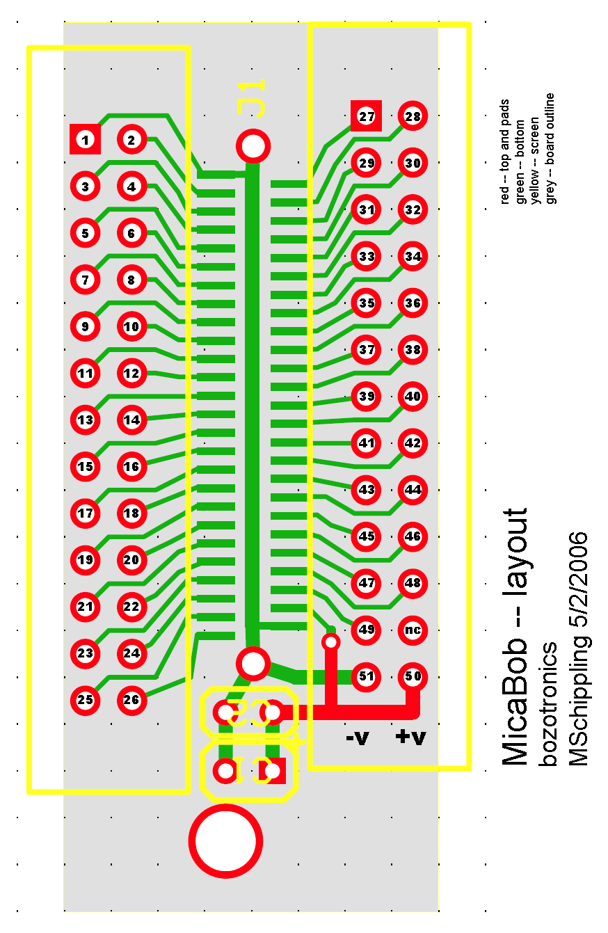
Anyway according to my layout, power should be coming
off of one end of the connector and the pin 42 ADC input
is about 1/3 of the way in from the power end. So the
wires coming out of the top of the card seem to be
in inappropriate locations. Here's my layout:
http://www.etantdonnes.com/Motes/MicaBOB/micaBOB_layout.png
per this:
>> If you are able to read the sensor-board Photo/Temp on ADC1
>> then I think there must be a connection issue with your BOB.
>
> What? I do not understand what you mean.
I meant that if you were successful in reading the sensor
board, where the Photo/Temp input is on ADC1, then there must
be something wrong with your break-out-board. Especially if you
use the same mote program in both cases. Trying the whole
thing again with a bare connector and getting your power directly
from the battery to minimize connector diddling might help point
you in the right direction.
MS
Francesco Ficarola wrote:
> Michael Schippling ha scritto:
>> Well, that photo is not very informative...
>
> Probably this photo is more informative:
> http://img683.imageshack.us/img683/2381/breakoutboardmini.jpg
>
>> and I notice that it's not actually my break-out board...
>
> No, it's not your bob, in fact I wrote that it is similar, not the same. :)
>
>> how do you have the connector mounted on that perf-board?
>
> Yes, Hirose DF9-51 pin
>
>> Are you sure you haven't shorted contacts on the connector?
>
> No, I tested it with a multimeter.
>
>> If you are able to read the sensor-board Photo/Temp on ADC1
>> then I think there must be a connection issue with your BOB.
>
> What? I do not understand what you mean.
>
>> Another thing to try, if you have a steady hand, is just
>> solder a wire (tiny wire-wrap wire has worked for me) to
>> a spare mating connector at -- I think -- pin 42 and run
>> that to your pot center.
>>
>> good luck
>> MS
>
> I'll try it, thanks.
>
> Greetings,
------------------------------
Message: 2
Date: Sun, 23 Jan 2011 03:04:26 +0400
From: firas obeidat <[email protected]>
Subject: [Tinyos-help] Micaz
To: <[email protected]>
Message-ID: <[email protected]>
Content-Type: text/plain; charset="windows-1256"
HI I am working on micaz,its for my 4th year project,and I encountered this
problem that even my profs cant solve it...
I am trying to send packets between mica z on the mica z radio in a specific
order so for ex: mica A send a packet to Mica B..
once Mica B receive this packet it sends a packet specifically to Mica C,then
Mica C receive it and send to Mica D.
Mica A->Mica B->Mica C->Mica D
but sometimes ESPECIALLY when I turn them all at once packet collusion occurs I
think..
so what happens is that when Mica A send to Mica B.Mica B receive it and sends
But mica C and D doesn't receive it even though Mica B is telling me that its
sending..
I think this might be related to interference between Mica A & B since they are
sending over the radio using the same frequency for all signals, am not sure
that's why I am really in need for an explanation..
the WEIRD part is if I turn mica A off then On again then they ALL WORK!! I
REALLY DONT KNOW WHY THIS FIXES THE PROBLEM
-------------- next part --------------
An HTML attachment was scrubbed...
URL:
https://www.millennium.berkeley.edu/pipermail/tinyos-help/attachments/20110123/3162fb61/attachment.html
------------------------------
Message: 3
Date: Sun, 23 Jan 2011 09:55:53 +0100
From: Francesco Ficarola <[email protected]>
Subject: Re: [Tinyos-help] ADC Readings and VoltageC
To: Michael Schippling <[email protected]>
Cc: TinyOS - Help <[email protected]>
Message-ID: <[email protected]>
Content-Type: text/plain; charset="iso-8859-1"
Michael Schippling ha scritto:
> The photo still doesn't help much...
> I'd like to see how the connector is mounted
> to the board and how the wires are then connected,
> but probably would have to be able to handle the
> actual object...
The connector is mounted to the board with only the solderings of the
VCC/ADC1/GND pins. They sustain the connector firmly.
> Anyway according to my layout, power should be coming
> off of one end of the connector and the pin 42 ADC input
> is about 1/3 of the way in from the power end. So the
> wires coming out of the top of the card seem to be
> in inappropriate locations. Here's my layout:
> http://www.etantdonnes.com/Motes/MicaBOB/micaBOB_layout.png
This photo is a zoom, so you can count the pins:
http://img267.imageshack.us/img267/8161/dsc0750cj.jpg
The connection seems right.
> I meant that if you were successful in reading the sensor
> board, where the Photo/Temp input is on ADC1, then there must
> be something wrong with your break-out-board.
One moment... Hence in IRIS mote the ADC1 channel is connected to
Photo/Temp? I can't connect a potentiometer?
> Especially if you
> use the same mote program in both cases. Trying the whole
> thing again with a bare connector and getting your power directly
> from the battery to minimize connector diddling might help point
> you in the right direction.
>
> MS
Thanks Michael.
Greetings,
--
Francesco Ficarola <francesco.ficarola_at_gmail_dot_com>
[GPG KeyID: 0xDBA99D92]
-------------- next part --------------
A non-text attachment was scrubbed...
Name: signature.asc
Type: application/pgp-signature
Size: 260 bytes
Desc: OpenPGP digital signature
Url :
https://www.millennium.berkeley.edu/pipermail/tinyos-help/attachments/20110123/a1976ee0/attachment-0001.pgp
------------------------------
Message: 4
Date: Sun, 23 Jan 2011 12:14:09 -0700
From: Michael Schippling <[email protected]>
Subject: Re: [Tinyos-help] ADC Readings and VoltageC
To: Francesco Ficarola <[email protected]>
Cc: TinyOS - Help <[email protected]>
Message-ID: <[email protected]>
Content-Type: text/plain; charset=ISO-8859-1; format=flowed
The previous photo from the top of the board, looked like the
red and blue wires (which I thought were the power) were
coming from the middle of the board and there were two black
wires coming from one end. That's what I meant about having
to actually be there to see what was what....
Anyway did you try the single wire on a bare connector thing?
The Photo/Temp sensor is on the micasb sensor board -- the
MTS300 or 310...I keep loosing track of the part numbers.
I think the MDA300 also has them, but can't find any actual
schematics.
The only ADC connections on the mica2,z boards themselves
are Voltage at ADC7 and RSSI at ADC0. I presume that the
IRIS board is the same, and also that it has the same
52 pin expansion layout.
I think you stated that you were able to read the sensor-
board Photo/Temp correctly, without Voltage value interference.
And also that you were able to read Voltage when there was no
sensor board attached. This leads me to believe that the
problem is in the element that changes: your break-out-board.
Probably the thing to do at this point is back-up to the
beginning and try everything again, changing only one element
-- both software and hardware -- at each step. Debugging
this stuff by remote control is basically impossible though.
MS
Francesco Ficarola wrote:
> Michael Schippling ha scritto:
>> The photo still doesn't help much...
>> I'd like to see how the connector is mounted
>> to the board and how the wires are then connected,
>> but probably would have to be able to handle the
>> actual object...
>
> The connector is mounted to the board with only the solderings of the
> VCC/ADC1/GND pins. They sustain the connector firmly.
>
>> Anyway according to my layout, power should be coming
>> off of one end of the connector and the pin 42 ADC input
>> is about 1/3 of the way in from the power end. So the
>> wires coming out of the top of the card seem to be
>> in inappropriate locations. Here's my layout:
>> http://www.etantdonnes.com/Motes/MicaBOB/micaBOB_layout.png
>
> This photo is a zoom, so you can count the pins:
> http://img267.imageshack.us/img267/8161/dsc0750cj.jpg
> The connection seems right.
>
>> I meant that if you were successful in reading the sensor
>> board, where the Photo/Temp input is on ADC1, then there must
>> be something wrong with your break-out-board.
>
> One moment... Hence in IRIS mote the ADC1 channel is connected to
> Photo/Temp? I can't connect a potentiometer?
>
>> Especially if you
>> use the same mote program in both cases. Trying the whole
>> thing again with a bare connector and getting your power directly
>> from the battery to minimize connector diddling might help point
>> you in the right direction.
>>
>> MS
>
> Thanks Michael.
>
> Greetings,
------------------------------
Message: 5
Date: Sun, 23 Jan 2011 12:32:48 -0700
From: Michael Schippling <[email protected]>
Subject: Re: [Tinyos-help] Micaz
To: firas obeidat <[email protected]>
Cc: [email protected]
Message-ID: <[email protected]>
Content-Type: text/plain; charset=windows-1256; format=flowed
Packet collision should be handled in the lower level radio code,
so you don't need to worry about it. Messages can be lost due to
noise, distance, or other interference, but it doesn't sound like
that's the problem if it works the second time around.
Maybe you need to wait a while before first sending your messages?
Put a second or two of Timer delay in the initiating mica-A after
power up?
Perhaps you can post your code so we can have a look.
MS
firas obeidat wrote:
> HI I am working on micaz,its for my 4th year project,and I encountered
> this problem that even my profs cant solve it...
> I am trying to send packets between mica z on the mica z radio in a
> specific order so for ex: mica A send a packet to Mica B..
> once Mica B receive this packet it sends a packet specifically to Mica
> C,then Mica C receive it and send to Mica D.
> Mica A->Mica B->Mica C->Mica D
> but sometimes ESPECIALLY when I turn them all at once packet collusion
> occurs I think..
> so what happens is that when Mica A send to Mica B.Mica B receive it and
> sends But mica C and D doesn't receive it even though Mica B is telling
> me that its sending..
> I think this might be related to interference between Mica A & B since
> they are sending over the radio using the same frequency for all
> signals, am not sure that's why I am really in need for an explanation..
> the WEIRD part is if I turn mica A off then On again then they ALL
> WORK!! I REALLY DONT KN! OW WHY THIS FIXES THE PROBLEM
>
>
> ------------------------------------------------------------------------
>
> _______________________________________________
> Tinyos-help mailing list
> [email protected]
> https://www.millennium.berkeley.edu/cgi-bin/mailman/listinfo/tinyos-help
------------------------------
_______________________________________________
Tinyos-help mailing list
[email protected]
https://www.millennium.berkeley.edu/cgi-bin/mailman/listinfo/tinyos-help
End of Tinyos-help Digest, Vol 93, Issue 50
*******************************************
_______________________________________________
Tinyos-help mailing list
[email protected]
https://www.millennium.berkeley.edu/cgi-bin/mailman/listinfo/tinyos-help