> 3- EMI/RFI has two components, electrical and magnetic field must be
> blocked. My RX antennas has low gain and they work near RX noise floor
> ,that
> requires a high gain preamp, my preamp has  >40 db gain. Aluminum boxes
> are
> not enough to kill the magnetic field noise from the PC and from my 2 LDC
> screen monitors, the solution was steel tinplated  24"x36"galvanized steel
> plate bellow the desk and to build a large box 20" x 30"  x 3" to install
> all preamps and the RX switches inside.
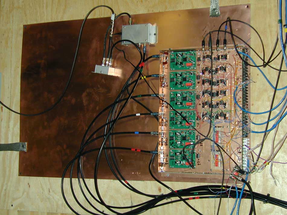
While this does exist at frequencies below where skin depth in shields
occurs, the "magnetic field thing" is a very common myth, or misconception,
with radio frequency signals.

A monitor with low frequency energy or transformer might be able to induce
very low frequency signals across a thin shield, and they might get into
circuits sensitive to low frequencies, but this takes special errors. This
is why audio system behavior cannot be applied to RF systems.

If we look at the thin copper sheet on this page:

http://www.w8ji.com/skindepth.htm

we see nothing penetrates the wall, once it is several skin-depths thick.

Neither magnetic nor electric fields will penetrate any shield or wall more
than several skin depths thick, no matter what conductive material the
shield or wall is made from.

This is why the foil layer on CATV cable is so effective. While a braid
weaves in and out, and current from the outer wall can weave in and out once
the braid tarnishes or becomes "unpacked", it doesn't matter how "dirty" a
solid wall becomes. All we need is good electrical integrity to the
connector shell at each end, many skin depths of thickness, and the shield
system is very effective.

This is also why metal boxes with properly mounted connectors are necessary
in high noise environments, although a proper groundplane (with properly
mounted connectors) can be almost as effective. My antenna distribution and
group system switching system is an open groundplane construction, and has
no measureable noise ingress.

http://www.w8ji.com/images/New%20Contest%20Room/Contest%20station%20CQWW2007/receiver-switch-matrix.jpg

Note the connectors are not mounted on plastic with grounding leads entering
the area of electronics, but are mounted on the groundplane formed by the
5-sided box that houses the amplifiers and relays. The groundplane prevents
common mode from exciting the internal point-to-point wiring, so I can use
twisted-pair enamel wiring inside the matrix for space and speed.

What goes through the shield of a shielded loop antenna? Nothing at all, not
the magnetic or electric fields. The shield is the actual antenna, and it
couples to the inner conductor via the voltage across the gap. That's why a
"shielded loop" has to have perfect shield symmetry, or it has common mode
issues.

If you install a device built with a plastic box, especially without a solid
groundplane, it is guaranteed to have common mode issues.

On the other hand even an open housing (like I use in my switching matrix)
is OK, if the backplane has integrity and the connectors mount properly.

73 Tom

_______________________________________________
UR RST IS ... ... ..9 QSB QSB - hw? BK