On 3/8/24 22:48, E Shattow wrote:
Yes this reference to GPIO high/low states is clearer to understand.
Have you tested the DIP switch functionality to confirm?; It is not
shown in the MilkV documentation or outdated schematics and I don't have
a Mars to test. I did find function descriptions from what is likely
cut-and-paste of VisionFive2 board reference.
Ref:
https://github.com/milkv-mars/mars-files/blob/main/Mars_hardware_schematics/Mars_V1.11_20230821.pdf <https://github.com/milkv-mars/mars-files/blob/main/Mars_hardware_schematics/Mars_V1.11_20230821.pdf> Sheet 7 of 22 JH7110 GPIOs
There is a schematic for SW2 (bootloader button?) that lists an inset table:
* - GPIO_1
   - GPIO_0
   - Boot
* - 0
   - 0
   - Flash
* - 0
   - 1
   - SD
* - 1
   - 0
   - eMMC
* - 1
   - 1
   - UART
That circuit on SW2 appears to pull high both RGPIO_1 and RGPIO_0 with
transistors. Again, no DIP switch as this is an earlier revision.
Ref:
https://doc-en.rvspace.org/VisionFive2/Developer_Guide/JH7110_Boot_UG.pdf <https://doc-en.rvspace.org/VisionFive2/Developer_Guide/JH7110_Boot_UG.pdf> page 9 table 1-4:
RGPIO1=0x0 RGPIO0=0x0 Boot Source: Quad SPI NOR flash memory, Read SPL
from Sector 0.
RGPIO1=0x1 RGPIO0=0x1 Boot Source: UART0, (description of UART Xmodem
function).
Following in the same document on page 13 figure 2-1 Boot Flow:
JH7110supportsthefollowingbootdevices.
QSPIFlash(ForSPL + OpenSBI +
U-Boot)+NVMe/SDCard/eMMC(ForKernel+FileSystemandlater)
Note:
System will detect in sequence whether it can boot from the following
device sequence: NVMe > SD > eMMC.
For example,if the boot program is found on the SD, eMMC will be ignored.
The GPIOs select from where U-Boot SPL is loaded. Currently U-Boot SPL
loads main U-Boot from the same device. But you could change it to scan
multiple devices for main U-Boot.
Once you have successfully loaded main U-Boot, main U-Boot will scan the
different boot devices. This includes NVME, eMMC, SD, USB, Network.
Currently upstream U-Boot development is moving from hard coded
sequences in board files to configurable boot sequences.
Again in this document Figure 4-2 on page 17 is a visual listing of the
DIP switch positions for QSPI, SDIO, eMMC, and UART boot modes, of the
VisionFive2 board.
These are just the same switches as on the Milk-V.
The only consistent physical interface over VisionFive2, Mars, Star64,
Mars CM all is RGPIO1=L RGPIO0=L SPI and RGPIO1=H RGPIO1=H UART; either
by DIP switch or pushbutton attached circuit. So, I question our
assumptions about what the actual behavior is for RGPIO1=H RGPIO0=L
pairing and RGPIO1=L RGPIO0=H, and in what circumstance would there be
followed a device sequence as suggested by the JH7110 reference. Why
does the StarFive documentation list a JH7110 boot device sequence if
there is also these H+L or L+H pairings to choose the device?
As said the device sequence including NVMe is not realized by the code
loading U-Boot SPL. It is realized in main U-Boot.
Best regards

Heinrich
On Thu, Mar 7, 2024 at 6:37 PM Heinrich Schuchardt
<[email protected]
<mailto:[email protected]>> wrote:
On 3/8/24 00:20, E Shattow wrote:
>
> On Sun, Mar 3, 2024 at 5:02 AM Heinrich Schuchardt
> <[email protected]
<mailto:[email protected]>
> <mailto:[email protected]
<mailto:[email protected]>>> wrote:
> ...
>
> +The board provides the DIP switches MSEL[1:0] to select the boot
> device out of
> +SPI flash, eMMC, SD-card, UART. To select booting from
SD-card set
> the DIP
> +switches MSEL[1:0] to 10.
>
>
> This does not match the [Milk-V Mars vendor
>
documentation](https://milkv.io/docs/mars/getting-started/bootloader
<https://milkv.io/docs/mars/getting-started/bootloader>
> <https://milkv.io/docs/mars/getting-started/bootloader
<https://milkv.io/docs/mars/getting-started/bootloader>>). Maybe you
have
> a different board revision?
Thank you for reviewing.
My board revision is V1.21 according to the silk screen.
The Milk-V Mars has DIP switches for the boot selection as shown in
https://gist.github.com/xypron/e28f95b1ed6911aeb9699ba63ae1a885
<https://gist.github.com/xypron/e28f95b1ed6911aeb9699ba63ae1a885>
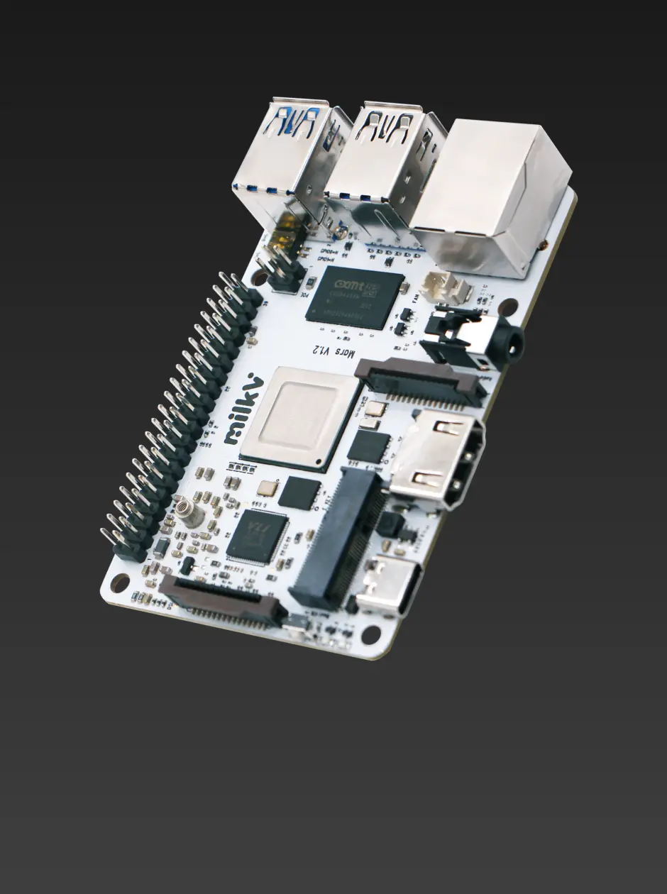
If you look at the photo
https://milkv.io/assets/images/mars-icon-04-e8814f18158a0e9d4387f4fa330693f1.webp
<https://milkv.io/assets/images/mars-icon-04-e8814f18158a0e9d4387f4fa330693f1.webp>
in the https://milkv.io/mars <https://milkv.io/mars> page, it also
shows DIP switches (in the
SPI-Flash position) on a rev 1.2 board.
Did you see a board without DIP switches being sold?
The silk screen markings on the board and the switch don't match.
The same confusion exists on the VisionFive2.
So maybe I should better write in a table:
SPI-Flash:
GPIO0=L
GPIO1=L
SD-Card:
GPIO0=H
GPIO1=L
eMMC:
GPIO0=L
GPIO1=H
UART:
GPIO0=H
GPIO1=H
Best regards
Heinrich