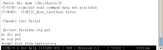
Now that we do not require device tree files to be built when
OF_OMIT_DTB is set, we can remove a number of unused dts files.
Signed-off-by: Tom Rini <[email protected]> --- arch/arm/dts/Makefile | 27 +- arch/arm/dts/arm_fvp.dts | 11 - arch/arm/dts/bcm2711-rpi-4-b.dts | 262 ----- arch/arm/dts/bcm2711-rpi.dtsi | 74 -- arch/arm/dts/bcm2711.dtsi | 1100 ------------------ arch/arm/dts/bcm2835-common.dtsi | 207 ---- arch/arm/dts/bcm2835-rpi-a-plus.dts | 128 -- arch/arm/dts/bcm2835-rpi-a.dts | 123 -- arch/arm/dts/bcm2835-rpi-b-plus.dts | 130 --- arch/arm/dts/bcm2835-rpi-b-rev2.dts | 123 -- arch/arm/dts/bcm2835-rpi-b.dts | 118 -- arch/arm/dts/bcm2835-rpi-cm1-io1.dts | 97 -- arch/arm/dts/bcm2835-rpi-cm1.dtsi | 39 - arch/arm/dts/bcm2835-rpi-common.dtsi | 12 - arch/arm/dts/bcm2835-rpi-zero-w.dts | 151 --- arch/arm/dts/bcm2835-rpi-zero.dts | 119 -- arch/arm/dts/bcm2835-rpi.dtsi | 81 -- arch/arm/dts/bcm2835.dtsi | 38 - arch/arm/dts/bcm2836-rpi-2-b.dts | 130 --- arch/arm/dts/bcm2836-rpi.dtsi | 6 - arch/arm/dts/bcm2836.dtsi | 92 -- arch/arm/dts/bcm2837-rpi-3-a-plus.dts | 180 --- arch/arm/dts/bcm2837-rpi-3-b-plus.dts | 183 --- arch/arm/dts/bcm2837-rpi-3-b.dts | 176 --- arch/arm/dts/bcm2837-rpi-cm3-io3.dts | 96 -- arch/arm/dts/bcm2837-rpi-cm3.dtsi | 61 - arch/arm/dts/bcm2837.dtsi | 95 -- arch/arm/dts/bcm283x-rpi-lan7515.dtsi | 41 - arch/arm/dts/bcm283x-rpi-smsc9512.dtsi | 20 - arch/arm/dts/bcm283x-rpi-smsc9514.dtsi | 19 - arch/arm/dts/bcm283x-rpi-usb-host.dtsi | 3 - arch/arm/dts/bcm283x-rpi-usb-otg.dtsi | 11 - arch/arm/dts/bcm283x-rpi-usb-peripheral.dtsi | 7 - arch/arm/dts/bcm283x-u-boot.dtsi | 29 - arch/arm/dts/bcm283x.dtsi | 501 -------- arch/arm/dts/bcm7xxx.dts | 15 - arch/arm/dts/highbank.dts | 9 - arch/arm/dts/octeontx.dts | 14 - arch/arm/dts/qemu-arm.dts | 11 - arch/arm/dts/xenguest-arm64.dts | 15 - 40 files changed, 1 insertion(+), 4553 deletions(-) delete mode 100644 arch/arm/dts/arm_fvp.dts delete mode 100644 arch/arm/dts/bcm2711-rpi-4-b.dts delete mode 100644 arch/arm/dts/bcm2711-rpi.dtsi delete mode 100644 arch/arm/dts/bcm2711.dtsi delete mode 100644 arch/arm/dts/bcm2835-common.dtsi delete mode 100644 arch/arm/dts/bcm2835-rpi-a-plus.dts delete mode 100644 arch/arm/dts/bcm2835-rpi-a.dts delete mode 100644 arch/arm/dts/bcm2835-rpi-b-plus.dts delete mode 100644 arch/arm/dts/bcm2835-rpi-b-rev2.dts delete mode 100644 arch/arm/dts/bcm2835-rpi-b.dts delete mode 100644 arch/arm/dts/bcm2835-rpi-cm1-io1.dts delete mode 100644 arch/arm/dts/bcm2835-rpi-cm1.dtsi delete mode 100644 arch/arm/dts/bcm2835-rpi-common.dtsi delete mode 100644 arch/arm/dts/bcm2835-rpi-zero-w.dts delete mode 100644 arch/arm/dts/bcm2835-rpi-zero.dts delete mode 100644 arch/arm/dts/bcm2835-rpi.dtsi delete mode 100644 arch/arm/dts/bcm2835.dtsi delete mode 100644 arch/arm/dts/bcm2836-rpi-2-b.dts delete mode 100644 arch/arm/dts/bcm2836-rpi.dtsi delete mode 100644 arch/arm/dts/bcm2836.dtsi delete mode 100644 arch/arm/dts/bcm2837-rpi-3-a-plus.dts delete mode 100644 arch/arm/dts/bcm2837-rpi-3-b-plus.dts delete mode 100644 arch/arm/dts/bcm2837-rpi-3-b.dts delete mode 100644 arch/arm/dts/bcm2837-rpi-cm3-io3.dts delete mode 100644 arch/arm/dts/bcm2837-rpi-cm3.dtsi delete mode 100644 arch/arm/dts/bcm2837.dtsi delete mode 100644 arch/arm/dts/bcm283x-rpi-lan7515.dtsi delete mode 100644 arch/arm/dts/bcm283x-rpi-smsc9512.dtsi delete mode 100644 arch/arm/dts/bcm283x-rpi-smsc9514.dtsi delete mode 100644 arch/arm/dts/bcm283x-rpi-usb-host.dtsi delete mode 100644 arch/arm/dts/bcm283x-rpi-usb-otg.dtsi delete mode 100644 arch/arm/dts/bcm283x-rpi-usb-peripheral.dtsi delete mode 100644 arch/arm/dts/bcm283x-u-boot.dtsi delete mode 100644 arch/arm/dts/bcm283x.dtsi delete mode 100644 arch/arm/dts/bcm7xxx.dts delete mode 100644 arch/arm/dts/highbank.dts delete mode 100644 arch/arm/dts/octeontx.dts delete mode 100644 arch/arm/dts/qemu-arm.dts delete mode 100644 arch/arm/dts/xenguest-arm64.dts diff --git a/arch/arm/dts/Makefile b/arch/arm/dts/Makefile index 25234697e6ae..78095e9b1922 100644 --- a/arch/arm/dts/Makefile +++ b/arch/arm/dts/Makefile @@ -835,8 +835,6 @@ dtb-$(CONFIG_MX7) += imx7d-sdb.dtb \ dtb-$(CONFIG_ARCH_MX7ULP) += imx7ulp-com.dtb \ imx7ulp-evk.dtb -dtb-$(CONFIG_ARCH_HIGHBANK) += highbank.dtb - dtb-$(CONFIG_ARCH_IMX8) += \ fsl-imx8qm-apalis.dtb \ fsl-imx8qm-mek.dtb \ @@ -963,28 +961,10 @@ dtb-$(CONFIG_TARGET_SAMA5D4_XPLAINED) += \ dtb-$(CONFIG_TARGET_VINCO) += \ at91-vinco.dtb -dtb-$(CONFIG_ARCH_BCM283X) += \ - bcm2835-rpi-a.dtb \ - bcm2835-rpi-a-plus.dtb \ - bcm2835-rpi-b.dtb \ - bcm2835-rpi-b-plus.dtb \ - bcm2835-rpi-b-rev2.dtb \ - bcm2835-rpi-cm1-io1.dtb \ - bcm2835-rpi-zero.dtb \ - bcm2835-rpi-zero-w.dtb\ - bcm2836-rpi-2-b.dtb \ - bcm2837-rpi-3-a-plus.dtb \ - bcm2837-rpi-3-b.dtb \ - bcm2837-rpi-3-b-plus.dtb \ - bcm2837-rpi-cm3-io3.dtb \ - bcm2711-rpi-4-b.dtb - dtb-$(CONFIG_TARGET_BCMNS) += ns-board.dtb dtb-$(CONFIG_TARGET_BCMNS3) += ns3-board.dtb -dtb-$(CONFIG_ARCH_BCMSTB) += bcm7xxx.dtb - dtb-$(CONFIG_BCM47622) += \ bcm947622.dtb dtb-$(CONFIG_BCM4908) += \ @@ -1099,10 +1079,6 @@ dtb-$(CONFIG_ARCH_MEDIATEK) += \ dtb-$(CONFIG_ARCH_NPCM7xx) += nuvoton-npcm750-evb.dtb dtb-$(CONFIG_ARCH_NPCM8XX) += nuvoton-npcm845-evb.dtb -dtb-$(CONFIG_XEN) += xenguest-arm64.dtb - -dtb-$(CONFIG_ARCH_OCTEONTX) += octeontx.dtb -dtb-$(CONFIG_ARCH_OCTEONTX2) += octeontx.dtb dtb-$(CONFIG_TARGET_GE_BX50V3) += \ imx6q-bx50v3.dtb \ @@ -1117,7 +1093,6 @@ dtb-$(CONFIG_TARGET_MX53PPD) += imx53-ppd.dtb # Kconfig option to build all of these. See examples above. dtb-$(CONFIG_TARGET_VEXPRESS_CA9X4) += vexpress-v2p-ca9.dtb dtb-$(CONFIG_TARGET_VEXPRESS64_BASE_FVP) += fvp-base-revc.dtb -dtb-$(CONFIG_TARGET_VEXPRESS64_BASER_FVP) += arm_fvp.dtb dtb-$(CONFIG_TARGET_VEXPRESS64_JUNO) += juno-r2.dtb dtb-$(CONFIG_TARGET_TOTAL_COMPUTE) += total_compute.dtb @@ -1163,7 +1138,7 @@ endif dtb-$(CONFIG_TARGET_EA_LPC3250DEVKITV2) += lpc3250-ea3250.dtb -dtb-$(CONFIG_ARCH_QEMU) += qemu-arm.dtb qemu-arm64.dtb +dtb-$(CONFIG_TARGET_QEMU_ARM_64BIT) += qemu-arm64.dtb dtb-$(CONFIG_TARGET_CORSTONE1000) += corstone1000-mps3.dtb \ corstone1000-fvp.dtb diff --git a/arch/arm/dts/arm_fvp.dts b/arch/arm/dts/arm_fvp.dts deleted file mode 100644 index 3a4ad5d18012..000000000000 --- a/arch/arm/dts/arm_fvp.dts +++ /dev/null @@ -1,11 +0,0 @@ -// SPDX-License-Identifier: GPL-2.0+ OR MIT -/* - * Empty device tree for the Arm Ltd FVP platform model - - * Copyright 2022 Arm Ltd. - */ - -/dts-v1/; - -/ { -}; diff --git a/arch/arm/dts/bcm2711-rpi-4-b.dts b/arch/arm/dts/bcm2711-rpi-4-b.dts deleted file mode 100644 index 72ce80fbf266..000000000000 --- a/arch/arm/dts/bcm2711-rpi-4-b.dts +++ /dev/null @@ -1,262 +0,0 @@ -// SPDX-License-Identifier: GPL-2.0 -/dts-v1/; -#include "bcm2711.dtsi" -#include "bcm2711-rpi.dtsi" -#include "bcm283x-rpi-usb-peripheral.dtsi" - -/ { - compatible = "raspberrypi,4-model-b", "brcm,bcm2711"; - model = "Raspberry Pi 4 Model B"; - - chosen { - /* 8250 auxiliary UART instead of pl011 */ - stdout-path = "serial1:115200n8"; - }; - - leds { - led-act { - gpios = <&gpio 42 GPIO_ACTIVE_HIGH>; - }; - - led-pwr { - label = "PWR"; - gpios = <&expgpio 2 GPIO_ACTIVE_LOW>; - default-state = "keep"; - linux,default-trigger = "default-on"; - }; - }; - - wifi_pwrseq: wifi-pwrseq { - compatible = "mmc-pwrseq-simple"; - reset-gpios = <&expgpio 1 GPIO_ACTIVE_LOW>; - }; - - sd_io_1v8_reg: sd_io_1v8_reg { - compatible = "regulator-gpio"; - regulator-name = "vdd-sd-io"; - regulator-min-microvolt = <1800000>; - regulator-max-microvolt = <3300000>; - regulator-boot-on; - regulator-always-on; - regulator-settling-time-us = <5000>; - gpios = <&expgpio 4 GPIO_ACTIVE_HIGH>; - states = <1800000 0x1>, - <3300000 0x0>; - status = "okay"; - }; - - sd_vcc_reg: sd_vcc_reg { - compatible = "regulator-fixed"; - regulator-name = "vcc-sd"; - regulator-min-microvolt = <3300000>; - regulator-max-microvolt = <3300000>; - regulator-boot-on; - enable-active-high; - gpio = <&expgpio 6 GPIO_ACTIVE_HIGH>; - }; -}; - -&ddc0 { - status = "okay"; -}; - -&ddc1 { - status = "okay"; -}; - -&expgpio { - gpio-line-names = "BT_ON", - "WL_ON", - "PWR_LED_OFF", - "GLOBAL_RESET", - "VDD_SD_IO_SEL", - "CAM_GPIO", - "SD_PWR_ON", - ""; -}; - -&gpio { - /* - * Parts taken from rpi_SCH_4b_4p0_reduced.pdf and - * the official GPU firmware DT blob. - * - * Legend: - * "FOO" = GPIO line named "FOO" on the schematic - * "FOO_N" = GPIO line named "FOO" on schematic, active low - */ - gpio-line-names = "ID_SDA", - "ID_SCL", - "SDA1", - "SCL1", - "GPIO_GCLK", - "GPIO5", - "GPIO6", - "SPI_CE1_N", - "SPI_CE0_N", - "SPI_MISO", - "SPI_MOSI", - "SPI_SCLK", - "GPIO12", - "GPIO13", - /* Serial port */ - "TXD1", - "RXD1", - "GPIO16", - "GPIO17", - "GPIO18", - "GPIO19", - "GPIO20", - "GPIO21", - "GPIO22", - "GPIO23", - "GPIO24", - "GPIO25", - "GPIO26", - "GPIO27", - "RGMII_MDIO", - "RGMIO_MDC", - /* Used by BT module */ - "CTS0", - "RTS0", - "TXD0", - "RXD0", - /* Used by Wifi */ - "SD1_CLK", - "SD1_CMD", - "SD1_DATA0", - "SD1_DATA1", - "SD1_DATA2", - "SD1_DATA3", - /* Shared with SPI flash */ - "PWM0_MISO", - "PWM1_MOSI", - "STATUS_LED_G_CLK", - "SPIFLASH_CE_N", - "SDA0", - "SCL0", - "RGMII_RXCLK", - "RGMII_RXCTL", - "RGMII_RXD0", - "RGMII_RXD1", - "RGMII_RXD2", - "RGMII_RXD3", - "RGMII_TXCLK", - "RGMII_TXCTL", - "RGMII_TXD0", - "RGMII_TXD1", - "RGMII_TXD2", - "RGMII_TXD3"; -}; - -&hdmi0 { - status = "okay"; -}; - -&hdmi1 { - status = "okay"; -}; - -&pixelvalve0 { - status = "okay"; -}; - -&pixelvalve1 { - status = "okay"; -}; - -&pixelvalve2 { - status = "okay"; -}; - -&pixelvalve4 { - status = "okay"; -}; - -&pwm1 { - pinctrl-names = "default"; - pinctrl-0 = <&pwm1_0_gpio40 &pwm1_1_gpio41>; - status = "okay"; -}; - -/* SDHCI is used to control the SDIO for wireless */ -&sdhci { - #address-cells = <1>; - #size-cells = <0>; - pinctrl-names = "default"; - pinctrl-0 = <&emmc_gpio34>; - bus-width = <4>; - non-removable; - mmc-pwrseq = <&wifi_pwrseq>; - status = "okay"; - - brcmf: wifi@1 { - reg = <1>; - compatible = "brcm,bcm4329-fmac"; - }; -}; - -/* EMMC2 is used to drive the SD card */ -&emmc2 { - vqmmc-supply = <&sd_io_1v8_reg>; - vmmc-supply = <&sd_vcc_reg>; - broken-cd; - status = "okay"; -}; - -&genet { - phy-handle = <&phy1>; - phy-mode = "rgmii-rxid"; - status = "okay"; -}; - -&genet_mdio { - phy1: ethernet-phy@1 { - /* No PHY interrupt */ - reg = <0x1>; - }; -}; - -&pcie0 { - pci@0,0 { - device_type = "pci"; - #address-cells = <3>; - #size-cells = <2>; - ranges; - - reg = <0 0 0 0 0>; - - usb@0,0 { - reg = <0 0 0 0 0>; - resets = <&reset RASPBERRYPI_FIRMWARE_RESET_ID_USB>; - }; - }; -}; - -/* uart0 communicates with the BT module */ -&uart0 { - pinctrl-names = "default"; - pinctrl-0 = <&uart0_ctsrts_gpio30 &uart0_gpio32>; - uart-has-rtscts; - status = "okay"; - - bluetooth { - compatible = "brcm,bcm43438-bt"; - max-speed = <2000000>; - shutdown-gpios = <&expgpio 0 GPIO_ACTIVE_HIGH>; - }; -}; - -/* uart1 is mapped to the pin header */ -&uart1 { - pinctrl-names = "default"; - pinctrl-0 = <&uart1_gpio14>; - status = "okay"; -}; - -&vc4 { - status = "okay"; -}; - -&vec { - status = "disabled"; -}; diff --git a/arch/arm/dts/bcm2711-rpi.dtsi b/arch/arm/dts/bcm2711-rpi.dtsi deleted file mode 100644 index ca266c5d9f9b..000000000000 --- a/arch/arm/dts/bcm2711-rpi.dtsi +++ /dev/null @@ -1,74 +0,0 @@ -// SPDX-License-Identifier: GPL-2.0 -#include "bcm2835-rpi.dtsi" - -#include <dt-bindings/reset/raspberrypi,firmware-reset.h> - -/ { - /* Will be filled by the bootloader */ - memory@0 { - device_type = "memory"; - reg = <0 0 0>; - }; - - aliases { - emmc2bus = &emmc2bus; - ethernet0 = &genet; - pcie0 = &pcie0; - blconfig = &blconfig; - }; -}; - -&firmware { - firmware_clocks: clocks { - compatible = "raspberrypi,firmware-clocks"; - #clock-cells = <1>; - }; - - expgpio: gpio { - compatible = "raspberrypi,firmware-gpio"; - gpio-controller; - #gpio-cells = <2>; - status = "okay"; - }; - - reset: reset { - compatible = "raspberrypi,firmware-reset"; - #reset-cells = <1>; - }; -}; - -&hdmi0 { - clocks = <&firmware_clocks 13>, <&firmware_clocks 14>, <&dvp 0>, <&clk_27MHz>; - clock-names = "hdmi", "bvb", "audio", "cec"; - wifi-2.4ghz-coexistence; -}; - -&hdmi1 { - clocks = <&firmware_clocks 13>, <&firmware_clocks 14>, <&dvp 1>, <&clk_27MHz>; - clock-names = "hdmi", "bvb", "audio", "cec"; - wifi-2.4ghz-coexistence; -}; - -&hvs { - clocks = <&firmware_clocks 4>; -}; - -&rmem { - /* - * RPi4's co-processor will copy the board's bootloader configuration - * into memory for the OS to consume. It'll also update this node with - * its placement information. - */ - blconfig: nvram@0 { - compatible = "raspberrypi,bootloader-config", "nvmem-rmem"; - #address-cells = <1>; - #size-cells = <1>; - reg = <0x0 0x0 0x0>; - no-map; - status = "disabled"; - }; -}; - -&vchiq { - interrupts = <GIC_SPI 34 IRQ_TYPE_LEVEL_HIGH>; -}; diff --git a/arch/arm/dts/bcm2711.dtsi b/arch/arm/dts/bcm2711.dtsi deleted file mode 100644 index 3b60297af7f6..000000000000 --- a/arch/arm/dts/bcm2711.dtsi +++ /dev/null @@ -1,1100 +0,0 @@ -// SPDX-License-Identifier: GPL-2.0 -#include "bcm283x.dtsi" - -#include <dt-bindings/interrupt-controller/arm-gic.h> -#include <dt-bindings/soc/bcm2835-pm.h> - -/ { - compatible = "brcm,bcm2711"; - - #address-cells = <2>; - #size-cells = <1>; - - interrupt-parent = <&gicv2>; - - vc4: gpu { - compatible = "brcm,bcm2711-vc5"; - status = "disabled"; - }; - - clk_27MHz: clk-27M { - #clock-cells = <0>; - compatible = "fixed-clock"; - clock-frequency = <27000000>; - clock-output-names = "27MHz-clock"; - }; - - clk_108MHz: clk-108M { - #clock-cells = <0>; - compatible = "fixed-clock"; - clock-frequency = <108000000>; - clock-output-names = "108MHz-clock"; - }; - - soc { - /* - * Defined ranges: - * Common BCM283x peripherals - * BCM2711-specific peripherals - * ARM-local peripherals - */ - ranges = <0x7e000000 0x0 0xfe000000 0x01800000>, - <0x7c000000 0x0 0xfc000000 0x02000000>, - <0x40000000 0x0 0xff800000 0x00800000>; - /* Emulate a contiguous 30-bit address range for DMA */ - dma-ranges = <0xc0000000 0x0 0x00000000 0x40000000>; - - /* - * This node is the provider for the enable-method for - * bringing up secondary cores. - */ - local_intc: local_intc@40000000 { - compatible = "brcm,bcm2836-l1-intc"; - reg = <0x40000000 0x100>; - }; - - gicv2: interrupt-controller@40041000 { - interrupt-controller; - #interrupt-cells = <3>; - compatible = "arm,gic-400"; - reg = <0x40041000 0x1000>, - <0x40042000 0x2000>, - <0x40044000 0x2000>, - <0x40046000 0x2000>; - interrupts = <GIC_PPI 9 (GIC_CPU_MASK_SIMPLE(4) | - IRQ_TYPE_LEVEL_HIGH)>; - }; - - avs_monitor: avs-monitor@7d5d2000 { - compatible = "brcm,bcm2711-avs-monitor", - "syscon", "simple-mfd"; - reg = <0x7d5d2000 0xf00>; - - thermal: thermal { - compatible = "brcm,bcm2711-thermal"; - #thermal-sensor-cells = <0>; - }; - }; - - dma: dma@7e007000 { - compatible = "brcm,bcm2835-dma"; - reg = <0x7e007000 0xb00>; - interrupts = <GIC_SPI 80 IRQ_TYPE_LEVEL_HIGH>, - <GIC_SPI 81 IRQ_TYPE_LEVEL_HIGH>, - <GIC_SPI 82 IRQ_TYPE_LEVEL_HIGH>, - <GIC_SPI 83 IRQ_TYPE_LEVEL_HIGH>, - <GIC_SPI 84 IRQ_TYPE_LEVEL_HIGH>, - <GIC_SPI 85 IRQ_TYPE_LEVEL_HIGH>, - <GIC_SPI 86 IRQ_TYPE_LEVEL_HIGH>, - /* DMA lite 7 - 10 */ - <GIC_SPI 87 IRQ_TYPE_LEVEL_HIGH>, - <GIC_SPI 87 IRQ_TYPE_LEVEL_HIGH>, - <GIC_SPI 88 IRQ_TYPE_LEVEL_HIGH>, - <GIC_SPI 88 IRQ_TYPE_LEVEL_HIGH>; - interrupt-names = "dma0", - "dma1", - "dma2", - "dma3", - "dma4", - "dma5", - "dma6", - "dma7", - "dma8", - "dma9", - "dma10"; - #dma-cells = <1>; - brcm,dma-channel-mask = <0x07f5>; - }; - - pm: watchdog@7e100000 { - compatible = "brcm,bcm2835-pm", "brcm,bcm2835-pm-wdt"; - #power-domain-cells = <1>; - #reset-cells = <1>; - reg = <0x7e100000 0x114>, - <0x7e00a000 0x24>, - <0x7ec11000 0x20>; - clocks = <&clocks BCM2835_CLOCK_V3D>, - <&clocks BCM2835_CLOCK_PERI_IMAGE>, - <&clocks BCM2835_CLOCK_H264>, - <&clocks BCM2835_CLOCK_ISP>; - clock-names = "v3d", "peri_image", "h264", "isp"; - system-power-controller; - }; - - rng@7e104000 { - compatible = "brcm,bcm2711-rng200"; - reg = <0x7e104000 0x28>; - }; - - uart2: serial@7e201400 { - compatible = "arm,pl011", "arm,primecell"; - reg = <0x7e201400 0x200>; - interrupts = <GIC_SPI 121 IRQ_TYPE_LEVEL_HIGH>; - clocks = <&clocks BCM2835_CLOCK_UART>, - <&clocks BCM2835_CLOCK_VPU>; - clock-names = "uartclk", "apb_pclk"; - arm,primecell-periphid = <0x00241011>; - status = "disabled"; - }; - - uart3: serial@7e201600 { - compatible = "arm,pl011", "arm,primecell"; - reg = <0x7e201600 0x200>; - interrupts = <GIC_SPI 121 IRQ_TYPE_LEVEL_HIGH>; - clocks = <&clocks BCM2835_CLOCK_UART>, - <&clocks BCM2835_CLOCK_VPU>; - clock-names = "uartclk", "apb_pclk"; - arm,primecell-periphid = <0x00241011>; - status = "disabled"; - }; - - uart4: serial@7e201800 { - compatible = "arm,pl011", "arm,primecell"; - reg = <0x7e201800 0x200>; - interrupts = <GIC_SPI 121 IRQ_TYPE_LEVEL_HIGH>; - clocks = <&clocks BCM2835_CLOCK_UART>, - <&clocks BCM2835_CLOCK_VPU>; - clock-names = "uartclk", "apb_pclk"; - arm,primecell-periphid = <0x00241011>; - status = "disabled"; - }; - - uart5: serial@7e201a00 { - compatible = "arm,pl011", "arm,primecell"; - reg = <0x7e201a00 0x200>; - interrupts = <GIC_SPI 121 IRQ_TYPE_LEVEL_HIGH>; - clocks = <&clocks BCM2835_CLOCK_UART>, - <&clocks BCM2835_CLOCK_VPU>; - clock-names = "uartclk", "apb_pclk"; - arm,primecell-periphid = <0x00241011>; - status = "disabled"; - }; - - spi3: spi@7e204600 { - compatible = "brcm,bcm2835-spi"; - reg = <0x7e204600 0x0200>; - interrupts = <GIC_SPI 118 IRQ_TYPE_LEVEL_HIGH>; - clocks = <&clocks BCM2835_CLOCK_VPU>; - #address-cells = <1>; - #size-cells = <0>; - status = "disabled"; - }; - - spi4: spi@7e204800 { - compatible = "brcm,bcm2835-spi"; - reg = <0x7e204800 0x0200>; - interrupts = <GIC_SPI 118 IRQ_TYPE_LEVEL_HIGH>; - clocks = <&clocks BCM2835_CLOCK_VPU>; - #address-cells = <1>; - #size-cells = <0>; - status = "disabled"; - }; - - spi5: spi@7e204a00 { - compatible = "brcm,bcm2835-spi"; - reg = <0x7e204a00 0x0200>; - interrupts = <GIC_SPI 118 IRQ_TYPE_LEVEL_HIGH>; - clocks = <&clocks BCM2835_CLOCK_VPU>; - #address-cells = <1>; - #size-cells = <0>; - status = "disabled"; - }; - - spi6: spi@7e204c00 { - compatible = "brcm,bcm2835-spi"; - reg = <0x7e204c00 0x0200>; - interrupts = <GIC_SPI 118 IRQ_TYPE_LEVEL_HIGH>; - clocks = <&clocks BCM2835_CLOCK_VPU>; - #address-cells = <1>; - #size-cells = <0>; - status = "disabled"; - }; - - i2c3: i2c@7e205600 { - compatible = "brcm,bcm2711-i2c", "brcm,bcm2835-i2c"; - reg = <0x7e205600 0x200>; - interrupts = <GIC_SPI 117 IRQ_TYPE_LEVEL_HIGH>; - clocks = <&clocks BCM2835_CLOCK_VPU>; - #address-cells = <1>; - #size-cells = <0>; - status = "disabled"; - }; - - i2c4: i2c@7e205800 { - compatible = "brcm,bcm2711-i2c", "brcm,bcm2835-i2c"; - reg = <0x7e205800 0x200>; - interrupts = <GIC_SPI 117 IRQ_TYPE_LEVEL_HIGH>; - clocks = <&clocks BCM2835_CLOCK_VPU>; - #address-cells = <1>; - #size-cells = <0>; - status = "disabled"; - }; - - i2c5: i2c@7e205a00 { - compatible = "brcm,bcm2711-i2c", "brcm,bcm2835-i2c"; - reg = <0x7e205a00 0x200>; - interrupts = <GIC_SPI 117 IRQ_TYPE_LEVEL_HIGH>; - clocks = <&clocks BCM2835_CLOCK_VPU>; - #address-cells = <1>; - #size-cells = <0>; - status = "disabled"; - }; - - i2c6: i2c@7e205c00 { - compatible = "brcm,bcm2711-i2c", "brcm,bcm2835-i2c"; - reg = <0x7e205c00 0x200>; - interrupts = <GIC_SPI 117 IRQ_TYPE_LEVEL_HIGH>; - clocks = <&clocks BCM2835_CLOCK_VPU>; - #address-cells = <1>; - #size-cells = <0>; - status = "disabled"; - }; - - pixelvalve0: pixelvalve@7e206000 { - compatible = "brcm,bcm2711-pixelvalve0"; - reg = <0x7e206000 0x100>; - interrupts = <GIC_SPI 109 IRQ_TYPE_LEVEL_HIGH>; - status = "disabled"; - }; - - pixelvalve1: pixelvalve@7e207000 { - compatible = "brcm,bcm2711-pixelvalve1"; - reg = <0x7e207000 0x100>; - interrupts = <GIC_SPI 110 IRQ_TYPE_LEVEL_HIGH>; - status = "disabled"; - }; - - pixelvalve2: pixelvalve@7e20a000 { - compatible = "brcm,bcm2711-pixelvalve2"; - reg = <0x7e20a000 0x100>; - interrupts = <GIC_SPI 101 IRQ_TYPE_LEVEL_HIGH>; - status = "disabled"; - }; - - pwm1: pwm@7e20c800 { - compatible = "brcm,bcm2835-pwm"; - reg = <0x7e20c800 0x28>; - clocks = <&clocks BCM2835_CLOCK_PWM>; - assigned-clocks = <&clocks BCM2835_CLOCK_PWM>; - assigned-clock-rates = <10000000>; - #pwm-cells = <2>; - status = "disabled"; - }; - - pixelvalve4: pixelvalve@7e216000 { - compatible = "brcm,bcm2711-pixelvalve4"; - reg = <0x7e216000 0x100>; - interrupts = <GIC_SPI 110 IRQ_TYPE_LEVEL_HIGH>; - status = "disabled"; - }; - - hvs: hvs@7e400000 { - compatible = "brcm,bcm2711-hvs"; - interrupts = <GIC_SPI 97 IRQ_TYPE_LEVEL_HIGH>; - }; - - pixelvalve3: pixelvalve@7ec12000 { - compatible = "brcm,bcm2711-pixelvalve3"; - reg = <0x7ec12000 0x100>; - interrupts = <GIC_SPI 106 IRQ_TYPE_LEVEL_HIGH>; - status = "disabled"; - }; - - vec: vec@7ec13000 { - compatible = "brcm,bcm2711-vec"; - reg = <0x7ec13000 0x1000>; - clocks = <&clocks BCM2835_CLOCK_VEC>; - interrupts = <GIC_SPI 123 IRQ_TYPE_LEVEL_HIGH>; - status = "disabled"; - }; - - dvp: clock@7ef00000 { - compatible = "brcm,brcm2711-dvp"; - reg = <0x7ef00000 0x10>; - clocks = <&clk_108MHz>; - #clock-cells = <1>; - #reset-cells = <1>; - }; - - aon_intr: interrupt-controller@7ef00100 { - compatible = "brcm,bcm2711-l2-intc", "brcm,l2-intc"; - reg = <0x7ef00100 0x30>; - interrupts = <GIC_SPI 96 IRQ_TYPE_LEVEL_HIGH>; - interrupt-controller; - #interrupt-cells = <1>; - }; - - hdmi0: hdmi@7ef00700 { - compatible = "brcm,bcm2711-hdmi0"; - reg = <0x7ef00700 0x300>, - <0x7ef00300 0x200>, - <0x7ef00f00 0x80>, - <0x7ef00f80 0x80>, - <0x7ef01b00 0x200>, - <0x7ef01f00 0x400>, - <0x7ef00200 0x80>, - <0x7ef04300 0x100>, - <0x7ef20000 0x100>; - reg-names = "hdmi", - "dvp", - "phy", - "rm", - "packet", - "metadata", - "csc", - "cec", - "hd"; - clock-names = "hdmi", "bvb", "audio", "cec"; - resets = <&dvp 0>; - interrupt-parent = <&aon_intr>; - interrupts = <0>, <1>, <2>, - <3>, <4>, <5>; - interrupt-names = "cec-tx", "cec-rx", "cec-low", - "wakeup", "hpd-connected", "hpd-removed"; - ddc = <&ddc0>; - dmas = <&dma 10>; - dma-names = "audio-rx"; - status = "disabled"; - }; - - ddc0: i2c@7ef04500 { - compatible = "brcm,bcm2711-hdmi-i2c"; - reg = <0x7ef04500 0x100>, <0x7ef00b00 0x300>; - reg-names = "bsc", "auto-i2c"; - clock-frequency = <97500>; - status = "disabled"; - }; - - hdmi1: hdmi@7ef05700 { - compatible = "brcm,bcm2711-hdmi1"; - reg = <0x7ef05700 0x300>, - <0x7ef05300 0x200>, - <0x7ef05f00 0x80>, - <0x7ef05f80 0x80>, - <0x7ef06b00 0x200>, - <0x7ef06f00 0x400>, - <0x7ef00280 0x80>, - <0x7ef09300 0x100>, - <0x7ef20000 0x100>; - reg-names = "hdmi", - "dvp", - "phy", - "rm", - "packet", - "metadata", - "csc", - "cec", - "hd"; - ddc = <&ddc1>; - clock-names = "hdmi", "bvb", "audio", "cec"; - resets = <&dvp 1>; - interrupt-parent = <&aon_intr>; - interrupts = <8>, <7>, <6>, - <9>, <10>, <11>; - interrupt-names = "cec-tx", "cec-rx", "cec-low", - "wakeup", "hpd-connected", "hpd-removed"; - dmas = <&dma 17>; - dma-names = "audio-rx"; - status = "disabled"; - }; - - ddc1: i2c@7ef09500 { - compatible = "brcm,bcm2711-hdmi-i2c"; - reg = <0x7ef09500 0x100>, <0x7ef05b00 0x300>; - reg-names = "bsc", "auto-i2c"; - clock-frequency = <97500>; - status = "disabled"; - }; - }; - - /* - * emmc2 has different DMA constraints based on SoC revisions. It was - * moved into its own bus, so as for RPi4's firmware to update them. - * The firmware will find whether the emmc2bus alias is defined, and if - * so, it'll edit the dma-ranges property below accordingly. - */ - emmc2bus: emmc2bus { - compatible = "simple-bus"; - #address-cells = <2>; - #size-cells = <1>; - - ranges = <0x0 0x7e000000 0x0 0xfe000000 0x01800000>; - dma-ranges = <0x0 0xc0000000 0x0 0x00000000 0x40000000>; - - emmc2: mmc@7e340000 { - compatible = "brcm,bcm2711-emmc2"; - reg = <0x0 0x7e340000 0x100>; - interrupts = <GIC_SPI 126 IRQ_TYPE_LEVEL_HIGH>; - clocks = <&clocks BCM2711_CLOCK_EMMC2>; - status = "disabled"; - }; - }; - - arm-pmu { - compatible = "arm,cortex-a72-pmu", "arm,armv8-pmuv3"; - interrupts = <GIC_SPI 16 IRQ_TYPE_LEVEL_HIGH>, - <GIC_SPI 17 IRQ_TYPE_LEVEL_HIGH>, - <GIC_SPI 18 IRQ_TYPE_LEVEL_HIGH>, - <GIC_SPI 19 IRQ_TYPE_LEVEL_HIGH>; - interrupt-affinity = <&cpu0>, <&cpu1>, <&cpu2>, <&cpu3>; - }; - - timer { - compatible = "arm,armv8-timer"; - interrupts = <GIC_PPI 13 (GIC_CPU_MASK_SIMPLE(4) | - IRQ_TYPE_LEVEL_LOW)>, - <GIC_PPI 14 (GIC_CPU_MASK_SIMPLE(4) | - IRQ_TYPE_LEVEL_LOW)>, - <GIC_PPI 11 (GIC_CPU_MASK_SIMPLE(4) | - IRQ_TYPE_LEVEL_LOW)>, - <GIC_PPI 10 (GIC_CPU_MASK_SIMPLE(4) | - IRQ_TYPE_LEVEL_LOW)>; - /* This only applies to the ARMv7 stub */ - arm,cpu-registers-not-fw-configured; - }; - - cpus: cpus { - #address-cells = <1>; - #size-cells = <0>; - enable-method = "brcm,bcm2836-smp"; // for ARM 32-bit - - cpu0: cpu@0 { - device_type = "cpu"; - compatible = "arm,cortex-a72"; - reg = <0>; - enable-method = "spin-table"; - cpu-release-addr = <0x0 0x000000d8>; - }; - - cpu1: cpu@1 { - device_type = "cpu"; - compatible = "arm,cortex-a72"; - reg = <1>; - enable-method = "spin-table"; - cpu-release-addr = <0x0 0x000000e0>; - }; - - cpu2: cpu@2 { - device_type = "cpu"; - compatible = "arm,cortex-a72"; - reg = <2>; - enable-method = "spin-table"; - cpu-release-addr = <0x0 0x000000e8>; - }; - - cpu3: cpu@3 { - device_type = "cpu"; - compatible = "arm,cortex-a72"; - reg = <3>; - enable-method = "spin-table"; - cpu-release-addr = <0x0 0x000000f0>; - }; - }; - - scb { - compatible = "simple-bus"; - #address-cells = <2>; - #size-cells = <1>; - - ranges = <0x0 0x7c000000 0x0 0xfc000000 0x03800000>, - <0x6 0x00000000 0x6 0x00000000 0x40000000>; - - pcie0: pcie@7d500000 { - compatible = "brcm,bcm2711-pcie"; - reg = <0x0 0x7d500000 0x9310>; - device_type = "pci"; - #address-cells = <3>; - #interrupt-cells = <1>; - #size-cells = <2>; - interrupts = <GIC_SPI 148 IRQ_TYPE_LEVEL_HIGH>, - <GIC_SPI 148 IRQ_TYPE_LEVEL_HIGH>; - interrupt-names = "pcie", "msi"; - interrupt-map-mask = <0x0 0x0 0x0 0x7>; - interrupt-map = <0 0 0 1 &gicv2 GIC_SPI 143 - IRQ_TYPE_LEVEL_HIGH>; - msi-controller; - msi-parent = <&pcie0>; - - ranges = <0x02000000 0x0 0xf8000000 0x6 0x00000000 - 0x0 0x04000000>; - /* - * The wrapper around the PCIe block has a bug - * preventing it from accessing beyond the first 3GB of - * memory. - */ - dma-ranges = <0x02000000 0x0 0x00000000 0x0 0x00000000 - 0x0 0xc0000000>; - brcm,enable-ssc; - }; - - genet: ethernet@7d580000 { - compatible = "brcm,bcm2711-genet-v5"; - reg = <0x0 0x7d580000 0x10000>; - #address-cells = <0x1>; - #size-cells = <0x1>; - interrupts = <GIC_SPI 157 IRQ_TYPE_LEVEL_HIGH>, - <GIC_SPI 158 IRQ_TYPE_LEVEL_HIGH>; - status = "disabled"; - - genet_mdio: mdio@e14 { - compatible = "brcm,genet-mdio-v5"; - reg = <0xe14 0x8>; - reg-names = "mdio"; - #address-cells = <0x1>; - #size-cells = <0x0>; - }; - }; - }; -}; - -&clk_osc { - clock-frequency = <54000000>; -}; - -&clocks { - compatible = "brcm,bcm2711-cprman"; -}; - -&cpu_thermal { - coefficients = <(-487) 410040>; - thermal-sensors = <&thermal>; -}; - -&dsi0 { - interrupts = <GIC_SPI 100 IRQ_TYPE_LEVEL_HIGH>; -}; - -&dsi1 { - interrupts = <GIC_SPI 108 IRQ_TYPE_LEVEL_HIGH>; - compatible = "brcm,bcm2711-dsi1"; -}; - -&gpio { - compatible = "brcm,bcm2711-gpio"; - interrupts = <GIC_SPI 113 IRQ_TYPE_LEVEL_HIGH>, - <GIC_SPI 114 IRQ_TYPE_LEVEL_HIGH>, - <GIC_SPI 115 IRQ_TYPE_LEVEL_HIGH>, - <GIC_SPI 116 IRQ_TYPE_LEVEL_HIGH>; - - gpclk0_gpio49: gpclk0_gpio49 { - pin-gpclk { - pins = "gpio49"; - function = "alt1"; - bias-disable; - }; - }; - gpclk1_gpio50: gpclk1_gpio50 { - pin-gpclk { - pins = "gpio50"; - function = "alt1"; - bias-disable; - }; - }; - gpclk2_gpio51: gpclk2_gpio51 { - pin-gpclk { - pins = "gpio51"; - function = "alt1"; - bias-disable; - }; - }; - - i2c0_gpio46: i2c0_gpio46 { - pin-sda { - function = "alt0"; - pins = "gpio46"; - bias-pull-up; - }; - pin-scl { - function = "alt0"; - pins = "gpio47"; - bias-disable; - }; - }; - i2c1_gpio46: i2c1_gpio46 { - pin-sda { - function = "alt1"; - pins = "gpio46"; - bias-pull-up; - }; - pin-scl { - function = "alt1"; - pins = "gpio47"; - bias-disable; - }; - }; - i2c3_gpio2: i2c3_gpio2 { - pin-sda { - function = "alt5"; - pins = "gpio2"; - bias-pull-up; - }; - pin-scl { - function = "alt5"; - pins = "gpio3"; - bias-disable; - }; - }; - i2c3_gpio4: i2c3_gpio4 { - pin-sda { - function = "alt5"; - pins = "gpio4"; - bias-pull-up; - }; - pin-scl { - function = "alt5"; - pins = "gpio5"; - bias-disable; - }; - }; - i2c4_gpio6: i2c4_gpio6 { - pin-sda { - function = "alt5"; - pins = "gpio6"; - bias-pull-up; - }; - pin-scl { - function = "alt5"; - pins = "gpio7"; - bias-disable; - }; - }; - i2c4_gpio8: i2c4_gpio8 { - pin-sda { - function = "alt5"; - pins = "gpio8"; - bias-pull-up; - }; - pin-scl { - function = "alt5"; - pins = "gpio9"; - bias-disable; - }; - }; - i2c5_gpio10: i2c5_gpio10 { - pin-sda { - function = "alt5"; - pins = "gpio10"; - bias-pull-up; - }; - pin-scl { - function = "alt5"; - pins = "gpio11"; - bias-disable; - }; - }; - i2c5_gpio12: i2c5_gpio12 { - pin-sda { - function = "alt5"; - pins = "gpio12"; - bias-pull-up; - }; - pin-scl { - function = "alt5"; - pins = "gpio13"; - bias-disable; - }; - }; - i2c6_gpio0: i2c6_gpio0 { - pin-sda { - function = "alt5"; - pins = "gpio0"; - bias-pull-up; - }; - pin-scl { - function = "alt5"; - pins = "gpio1"; - bias-disable; - }; - }; - i2c6_gpio22: i2c6_gpio22 { - pin-sda { - function = "alt5"; - pins = "gpio22"; - bias-pull-up; - }; - pin-scl { - function = "alt5"; - pins = "gpio23"; - bias-disable; - }; - }; - i2c_slave_gpio8: i2c_slave_gpio8 { - pins-i2c-slave { - pins = "gpio8", - "gpio9", - "gpio10", - "gpio11"; - function = "alt3"; - }; - }; - - jtag_gpio48: jtag_gpio48 { - pins-jtag { - pins = "gpio48", - "gpio49", - "gpio50", - "gpio51", - "gpio52", - "gpio53"; - function = "alt4"; - }; - }; - - mii_gpio28: mii_gpio28 { - pins-mii { - pins = "gpio28", - "gpio29", - "gpio30", - "gpio31"; - function = "alt4"; - }; - }; - mii_gpio36: mii_gpio36 { - pins-mii { - pins = "gpio36", - "gpio37", - "gpio38", - "gpio39"; - function = "alt5"; - }; - }; - - pcm_gpio50: pcm_gpio50 { - pins-pcm { - pins = "gpio50", - "gpio51", - "gpio52", - "gpio53"; - function = "alt2"; - }; - }; - - pwm0_0_gpio12: pwm0_0_gpio12 { - pin-pwm { - pins = "gpio12"; - function = "alt0"; - bias-disable; - }; - }; - pwm0_0_gpio18: pwm0_0_gpio18 { - pin-pwm { - pins = "gpio18"; - function = "alt5"; - bias-disable; - }; - }; - pwm1_0_gpio40: pwm1_0_gpio40 { - pin-pwm { - pins = "gpio40"; - function = "alt0"; - bias-disable; - }; - }; - pwm0_1_gpio13: pwm0_1_gpio13 { - pin-pwm { - pins = "gpio13"; - function = "alt0"; - bias-disable; - }; - }; - pwm0_1_gpio19: pwm0_1_gpio19 { - pin-pwm { - pins = "gpio19"; - function = "alt5"; - bias-disable; - }; - }; - pwm1_1_gpio41: pwm1_1_gpio41 { - pin-pwm { - pins = "gpio41"; - function = "alt0"; - bias-disable; - }; - }; - pwm0_1_gpio45: pwm0_1_gpio45 { - pin-pwm { - pins = "gpio45"; - function = "alt0"; - bias-disable; - }; - }; - pwm0_0_gpio52: pwm0_0_gpio52 { - pin-pwm { - pins = "gpio52"; - function = "alt1"; - bias-disable; - }; - }; - pwm0_1_gpio53: pwm0_1_gpio53 { - pin-pwm { - pins = "gpio53"; - function = "alt1"; - bias-disable; - }; - }; - - rgmii_gpio35: rgmii_gpio35 { - pin-start-stop { - pins = "gpio35"; - function = "alt4"; - }; - pin-rx-ok { - pins = "gpio36"; - function = "alt4"; - }; - }; - rgmii_irq_gpio34: rgmii_irq_gpio34 { - pin-irq { - pins = "gpio34"; - function = "alt5"; - }; - }; - rgmii_irq_gpio39: rgmii_irq_gpio39 { - pin-irq { - pins = "gpio39"; - function = "alt4"; - }; - }; - rgmii_mdio_gpio28: rgmii_mdio_gpio28 { - pins-mdio { - pins = "gpio28", - "gpio29"; - function = "alt5"; - }; - }; - rgmii_mdio_gpio37: rgmii_mdio_gpio37 { - pins-mdio { - pins = "gpio37", - "gpio38"; - function = "alt4"; - }; - }; - - spi0_gpio46: spi0_gpio46 { - pins-spi { - pins = "gpio46", - "gpio47", - "gpio48", - "gpio49"; - function = "alt2"; - }; - }; - spi2_gpio46: spi2_gpio46 { - pins-spi { - pins = "gpio46", - "gpio47", - "gpio48", - "gpio49", - "gpio50"; - function = "alt5"; - }; - }; - spi3_gpio0: spi3_gpio0 { - pins-spi { - pins = "gpio0", - "gpio1", - "gpio2", - "gpio3"; - function = "alt3"; - }; - }; - spi4_gpio4: spi4_gpio4 { - pins-spi { - pins = "gpio4", - "gpio5", - "gpio6", - "gpio7"; - function = "alt3"; - }; - }; - spi5_gpio12: spi5_gpio12 { - pins-spi { - pins = "gpio12", - "gpio13", - "gpio14", - "gpio15"; - function = "alt3"; - }; - }; - spi6_gpio18: spi6_gpio18 { - pins-spi { - pins = "gpio18", - "gpio19", - "gpio20", - "gpio21"; - function = "alt3"; - }; - }; - - uart2_gpio0: uart2_gpio0 { - pin-tx { - pins = "gpio0"; - function = "alt4"; - bias-disable; - }; - pin-rx { - pins = "gpio1"; - function = "alt4"; - bias-pull-up; - }; - }; - uart2_ctsrts_gpio2: uart2_ctsrts_gpio2 { - pin-cts { - pins = "gpio2"; - function = "alt4"; - bias-pull-up; - }; - pin-rts { - pins = "gpio3"; - function = "alt4"; - bias-disable; - }; - }; - uart3_gpio4: uart3_gpio4 { - pin-tx { - pins = "gpio4"; - function = "alt4"; - bias-disable; - }; - pin-rx { - pins = "gpio5"; - function = "alt4"; - bias-pull-up; - }; - }; - uart3_ctsrts_gpio6: uart3_ctsrts_gpio6 { - pin-cts { - pins = "gpio6"; - function = "alt4"; - bias-pull-up; - }; - pin-rts { - pins = "gpio7"; - function = "alt4"; - bias-disable; - }; - }; - uart4_gpio8: uart4_gpio8 { - pin-tx { - pins = "gpio8"; - function = "alt4"; - bias-disable; - }; - pin-rx { - pins = "gpio9"; - function = "alt4"; - bias-pull-up; - }; - }; - uart4_ctsrts_gpio10: uart4_ctsrts_gpio10 { - pin-cts { - pins = "gpio10"; - function = "alt4"; - bias-pull-up; - }; - pin-rts { - pins = "gpio11"; - function = "alt4"; - bias-disable; - }; - }; - uart5_gpio12: uart5_gpio12 { - pin-tx { - pins = "gpio12"; - function = "alt4"; - bias-disable; - }; - pin-rx { - pins = "gpio13"; - function = "alt4"; - bias-pull-up; - }; - }; - uart5_ctsrts_gpio14: uart5_ctsrts_gpio14 { - pin-cts { - pins = "gpio14"; - function = "alt4"; - bias-pull-up; - }; - pin-rts { - pins = "gpio15"; - function = "alt4"; - bias-disable; - }; - }; -}; - -&rmem { - #address-cells = <2>; -}; - -&cma { - /* - * arm64 reserves the CMA by default somewhere in ZONE_DMA32, - * that's not good enough for the BCM2711 as some devices can - * only address the lower 1G of memory (ZONE_DMA). - */ - alloc-ranges = <0x0 0x00000000 0x40000000>; -}; - -&i2c0 { - compatible = "brcm,bcm2711-i2c", "brcm,bcm2835-i2c"; - interrupts = <GIC_SPI 117 IRQ_TYPE_LEVEL_HIGH>; -}; - -&i2c1 { - compatible = "brcm,bcm2711-i2c", "brcm,bcm2835-i2c"; - interrupts = <GIC_SPI 117 IRQ_TYPE_LEVEL_HIGH>; -}; - -&mailbox { - interrupts = <GIC_SPI 33 IRQ_TYPE_LEVEL_HIGH>; -}; - -&sdhci { - interrupts = <GIC_SPI 126 IRQ_TYPE_LEVEL_HIGH>; -}; - -&sdhost { - interrupts = <GIC_SPI 120 IRQ_TYPE_LEVEL_HIGH>; -}; - -&spi { - interrupts = <GIC_SPI 118 IRQ_TYPE_LEVEL_HIGH>; -}; - -&spi1 { - interrupts = <GIC_SPI 93 IRQ_TYPE_LEVEL_HIGH>; -}; - -&spi2 { - interrupts = <GIC_SPI 93 IRQ_TYPE_LEVEL_HIGH>; -}; - -&system_timer { - interrupts = <GIC_SPI 64 IRQ_TYPE_LEVEL_HIGH>, - <GIC_SPI 65 IRQ_TYPE_LEVEL_HIGH>, - <GIC_SPI 66 IRQ_TYPE_LEVEL_HIGH>, - <GIC_SPI 67 IRQ_TYPE_LEVEL_HIGH>; -}; - -&txp { - interrupts = <GIC_SPI 75 IRQ_TYPE_LEVEL_HIGH>; -}; - -&uart0 { - interrupts = <GIC_SPI 121 IRQ_TYPE_LEVEL_HIGH>; -}; - -&uart1 { - interrupts = <GIC_SPI 93 IRQ_TYPE_LEVEL_HIGH>; -}; - -&usb { - interrupts = <GIC_SPI 73 IRQ_TYPE_LEVEL_HIGH>; -}; - -&vec { - compatible = "brcm,bcm2711-vec"; - interrupts = <GIC_SPI 123 IRQ_TYPE_LEVEL_HIGH>; -}; diff --git a/arch/arm/dts/bcm2835-common.dtsi b/arch/arm/dts/bcm2835-common.dtsi deleted file mode 100644 index c25e797b9060..000000000000 --- a/arch/arm/dts/bcm2835-common.dtsi +++ /dev/null @@ -1,207 +0,0 @@ -// SPDX-License-Identifier: GPL-2.0 - -/* This include file covers the common peripherals and configuration between - * bcm2835, bcm2836 and bcm2837 implementations. - */ - -/ { - interrupt-parent = <&intc>; - - soc { - dma: dma@7e007000 { - compatible = "brcm,bcm2835-dma"; - reg = <0x7e007000 0xf00>; - interrupts = <1 16>, - <1 17>, - <1 18>, - <1 19>, - <1 20>, - <1 21>, - <1 22>, - <1 23>, - <1 24>, - <1 25>, - <1 26>, - /* dma channel 11-14 share one irq */ - <1 27>, - <1 27>, - <1 27>, - <1 27>, - /* unused shared irq for all channels */ - <1 28>; - interrupt-names = "dma0", - "dma1", - "dma2", - "dma3", - "dma4", - "dma5", - "dma6", - "dma7", - "dma8", - "dma9", - "dma10", - "dma11", - "dma12", - "dma13", - "dma14", - "dma-shared-all"; - #dma-cells = <1>; - brcm,dma-channel-mask = <0x7f35>; - }; - - intc: interrupt-controller@7e00b200 { - compatible = "brcm,bcm2835-armctrl-ic"; - reg = <0x7e00b200 0x200>; - interrupt-controller; - #interrupt-cells = <2>; - }; - - pm: watchdog@7e100000 { - compatible = "brcm,bcm2835-pm", "brcm,bcm2835-pm-wdt"; - #power-domain-cells = <1>; - #reset-cells = <1>; - reg = <0x7e100000 0x114>, - <0x7e00a000 0x24>; - clocks = <&clocks BCM2835_CLOCK_V3D>, - <&clocks BCM2835_CLOCK_PERI_IMAGE>, - <&clocks BCM2835_CLOCK_H264>, - <&clocks BCM2835_CLOCK_ISP>; - clock-names = "v3d", "peri_image", "h264", "isp"; - system-power-controller; - }; - - rng@7e104000 { - compatible = "brcm,bcm2835-rng"; - reg = <0x7e104000 0x10>; - interrupts = <2 29>; - }; - - pixelvalve@7e206000 { - compatible = "brcm,bcm2835-pixelvalve0"; - reg = <0x7e206000 0x100>; - interrupts = <2 13>; /* pwa0 */ - }; - - pixelvalve@7e207000 { - compatible = "brcm,bcm2835-pixelvalve1"; - reg = <0x7e207000 0x100>; - interrupts = <2 14>; /* pwa1 */ - }; - - thermal: thermal@7e212000 { - compatible = "brcm,bcm2835-thermal"; - reg = <0x7e212000 0x8>; - clocks = <&clocks BCM2835_CLOCK_TSENS>; - #thermal-sensor-cells = <0>; - status = "disabled"; - }; - - i2c2: i2c@7e805000 { - compatible = "brcm,bcm2835-i2c"; - reg = <0x7e805000 0x1000>; - interrupts = <2 21>; - clocks = <&clocks BCM2835_CLOCK_VPU>; - #address-cells = <1>; - #size-cells = <0>; - status = "okay"; - }; - - vec: vec@7e806000 { - compatible = "brcm,bcm2835-vec"; - reg = <0x7e806000 0x1000>; - clocks = <&clocks BCM2835_CLOCK_VEC>; - interrupts = <2 27>; - status = "disabled"; - }; - - pixelvalve@7e807000 { - compatible = "brcm,bcm2835-pixelvalve2"; - reg = <0x7e807000 0x100>; - interrupts = <2 10>; /* pixelvalve */ - }; - - hdmi: hdmi@7e902000 { - compatible = "brcm,bcm2835-hdmi"; - reg = <0x7e902000 0x600>, - <0x7e808000 0x100>; - interrupts = <2 8>, <2 9>; - ddc = <&i2c2>; - clocks = <&clocks BCM2835_PLLH_PIX>, - <&clocks BCM2835_CLOCK_HSM>; - clock-names = "pixel", "hdmi"; - dmas = <&dma 17>; - dma-names = "audio-rx"; - status = "disabled"; - }; - - v3d: v3d@7ec00000 { - compatible = "brcm,bcm2835-v3d"; - reg = <0x7ec00000 0x1000>; - interrupts = <1 10>; - }; - - vc4: gpu { - compatible = "brcm,bcm2835-vc4"; - }; - }; -}; - -&cpu_thermal { - thermal-sensors = <&thermal>; -}; - -&gpio { - i2c_slave_gpio18: i2c_slave_gpio18 { - brcm,pins = <18 19 20 21>; - brcm,function = <BCM2835_FSEL_ALT3>; - }; - - jtag_gpio4: jtag_gpio4 { - brcm,pins = <4 5 6 12 13>; - brcm,function = <BCM2835_FSEL_ALT5>; - }; - - pwm0_gpio12: pwm0_gpio12 { - brcm,pins = <12>; - brcm,function = <BCM2835_FSEL_ALT0>; - }; - pwm0_gpio18: pwm0_gpio18 { - brcm,pins = <18>; - brcm,function = <BCM2835_FSEL_ALT5>; - }; - pwm0_gpio40: pwm0_gpio40 { - brcm,pins = <40>; - brcm,function = <BCM2835_FSEL_ALT0>; - }; - pwm1_gpio13: pwm1_gpio13 { - brcm,pins = <13>; - brcm,function = <BCM2835_FSEL_ALT0>; - }; - pwm1_gpio19: pwm1_gpio19 { - brcm,pins = <19>; - brcm,function = <BCM2835_FSEL_ALT5>; - }; - pwm1_gpio41: pwm1_gpio41 { - brcm,pins = <41>; - brcm,function = <BCM2835_FSEL_ALT0>; - }; - pwm1_gpio45: pwm1_gpio45 { - brcm,pins = <45>; - brcm,function = <BCM2835_FSEL_ALT0>; - }; -}; - -&i2s { - dmas = <&dma 2>, <&dma 3>; - dma-names = "tx", "rx"; -}; - -&sdhost { - dmas = <&dma 13>; - dma-names = "rx-tx"; -}; - -&spi { - dmas = <&dma 6>, <&dma 7>; - dma-names = "tx", "rx"; -}; diff --git a/arch/arm/dts/bcm2835-rpi-a-plus.dts b/arch/arm/dts/bcm2835-rpi-a-plus.dts deleted file mode 100644 index 40b9405f1a8e..000000000000 --- a/arch/arm/dts/bcm2835-rpi-a-plus.dts +++ /dev/null @@ -1,128 +0,0 @@ -// SPDX-License-Identifier: GPL-2.0 -/dts-v1/; -#include "bcm2835.dtsi" -#include "bcm2835-rpi.dtsi" -#include "bcm283x-rpi-usb-host.dtsi" - -/ { - compatible = "raspberrypi,model-a-plus", "brcm,bcm2835"; - model = "Raspberry Pi Model A+"; - - memory@0 { - device_type = "memory"; - reg = <0 0x10000000>; - }; - - leds { - led-act { - gpios = <&gpio 47 GPIO_ACTIVE_HIGH>; - }; - - led-pwr { - label = "PWR"; - gpios = <&gpio 35 GPIO_ACTIVE_HIGH>; - default-state = "keep"; - linux,default-trigger = "default-on"; - }; - }; -}; - -&gpio { - /* - * This is based on the unreleased schematic for the Model A+. - * - * Legend: - * "NC" = not connected (no rail from the SoC) - * "FOO" = GPIO line named "FOO" on the schematic - * "FOO_N" = GPIO line named "FOO" on schematic, active low - */ - gpio-line-names = "ID_SDA", - "ID_SCL", - "SDA1", - "SCL1", - "GPIO_GCLK", - "GPIO5", - "GPIO6", - "SPI_CE1_N", - "SPI_CE0_N", - "SPI_MISO", - "SPI_MOSI", - "SPI_SCLK", - "GPIO12", - "GPIO13", - /* Serial port */ - "TXD0", - "RXD0", - "GPIO16", - "GPIO17", - "GPIO18", - "GPIO19", - "GPIO20", - "GPIO21", - "GPIO22", - "GPIO23", - "GPIO24", - "GPIO25", - "GPIO26", - "GPIO27", - "SDA0", - "SCL0", - "NC", /* GPIO30 */ - "NC", /* GPIO31 */ - "CAM_GPIO1", /* GPIO32 */ - "NC", /* GPIO33 */ - "NC", /* GPIO34 */ - "PWR_LOW_N", /* GPIO35 */ - "NC", /* GPIO36 */ - "NC", /* GPIO37 */ - "USB_LIMIT", /* GPIO38 */ - "NC", /* GPIO39 */ - "PWM0_OUT", /* GPIO40 */ - "CAM_GPIO0", /* GPIO41 */ - "NC", /* GPIO42 */ - "NC", /* GPIO43 */ - "NC", /* GPIO44 */ - "PWM1_OUT", /* GPIO45 */ - "HDMI_HPD_N", - "STATUS_LED", - /* Used by SD Card */ - "SD_CLK_R", - "SD_CMD_R", - "SD_DATA0_R", - "SD_DATA1_R", - "SD_DATA2_R", - "SD_DATA3_R"; - - pinctrl-0 = <&gpioout &alt0 &i2s_alt0>; - - /* I2S interface */ - i2s_alt0: i2s_alt0 { - brcm,pins = <18 19 20 21>; - brcm,function = <BCM2835_FSEL_ALT0>; - }; -}; - -&hdmi { - hpd-gpios = <&gpio 46 GPIO_ACTIVE_LOW>; - power-domains = <&power RPI_POWER_DOMAIN_HDMI>; - status = "okay"; -}; - -&pwm { - pinctrl-names = "default"; - pinctrl-0 = <&pwm0_gpio40 &pwm1_gpio45>; - status = "okay"; -}; - -&sdhost { - pinctrl-names = "default"; - pinctrl-0 = <&sdhost_gpio48>; - bus-width = <4>; - status = "okay"; -}; - -&uart0 { - pinctrl-names = "default"; - pinctrl-0 = <&uart0_gpio14>; - status = "okay"; -}; diff --git a/arch/arm/dts/bcm2835-rpi-a.dts b/arch/arm/dts/bcm2835-rpi-a.dts deleted file mode 100644 index 11edb581dbaf..000000000000 --- a/arch/arm/dts/bcm2835-rpi-a.dts +++ /dev/null @@ -1,123 +0,0 @@ -// SPDX-License-Identifier: GPL-2.0 -/dts-v1/; -#include "bcm2835.dtsi" -#include "bcm2835-rpi.dtsi" -#include "bcm283x-rpi-usb-host.dtsi" - -/ { - compatible = "raspberrypi,model-a", "brcm,bcm2835"; - model = "Raspberry Pi Model A"; - - memory@0 { - device_type = "memory"; - reg = <0 0x10000000>; - }; - - leds { - led-act { - gpios = <&gpio 16 GPIO_ACTIVE_LOW>; - }; - }; -}; - -&gpio { - /* - * Taken from Raspberry-Pi-Rev-1.0-Model-AB-Schematics.pdf - * RPI00021 sheet 02 - * - * Legend: - * "NC" = not connected (no rail from the SoC) - * "FOO" = GPIO line named "FOO" on the schematic - * "FOO_N" = GPIO line named "FOO" on schematic, active low - */ - gpio-line-names = "SDA0", - "SCL0", - "SDA1", - "SCL1", - "GPIO_GCLK", - "CAM_GPIO1", - "LAN_RUN", - "SPI_CE1_N", - "SPI_CE0_N", - "SPI_MISO", - "SPI_MOSI", - "SPI_SCLK", - "NC", /* GPIO12 */ - "NC", /* GPIO13 */ - /* Serial port */ - "TXD0", - "RXD0", - "STATUS_LED_N", - "GPIO17", - "GPIO18", - "NC", /* GPIO19 */ - "NC", /* GPIO20 */ - "GPIO21", - "GPIO22", - "GPIO23", - "GPIO24", - "GPIO25", - "NC", /* GPIO26 */ - "CAM_GPIO0", - /* Binary number representing build/revision */ - "CONFIG0", - "CONFIG1", - "CONFIG2", - "CONFIG3", - "NC", /* GPIO32 */ - "NC", /* GPIO33 */ - "NC", /* GPIO34 */ - "NC", /* GPIO35 */ - "NC", /* GPIO36 */ - "NC", /* GPIO37 */ - "NC", /* GPIO38 */ - "NC", /* GPIO39 */ - "PWM0_OUT", - "NC", /* GPIO41 */ - "NC", /* GPIO42 */ - "NC", /* GPIO43 */ - "NC", /* GPIO44 */ - "PWM1_OUT", - "HDMI_HPD_P", - "SD_CARD_DET", - /* Used by SD Card */ - "SD_CLK_R", - "SD_CMD_R", - "SD_DATA0_R", - "SD_DATA1_R", - "SD_DATA2_R", - "SD_DATA3_R"; - - pinctrl-0 = <&gpioout &alt0 &i2s_alt2>; - - /* I2S interface */ - i2s_alt2: i2s_alt2 { - brcm,pins = <28 29 30 31>; - brcm,function = <BCM2835_FSEL_ALT2>; - }; -}; - -&hdmi { - hpd-gpios = <&gpio 46 GPIO_ACTIVE_HIGH>; - power-domains = <&power RPI_POWER_DOMAIN_HDMI>; - status = "okay"; -}; - -&pwm { - pinctrl-names = "default"; - pinctrl-0 = <&pwm0_gpio40 &pwm1_gpio45>; - status = "okay"; -}; - -&sdhost { - pinctrl-names = "default"; - pinctrl-0 = <&sdhost_gpio48>; - bus-width = <4>; - status = "okay"; -}; - -&uart0 { - pinctrl-names = "default"; - pinctrl-0 = <&uart0_gpio14>; - status = "okay"; -}; diff --git a/arch/arm/dts/bcm2835-rpi-b-plus.dts b/arch/arm/dts/bcm2835-rpi-b-plus.dts deleted file mode 100644 index 1b435c64bd9c..000000000000 --- a/arch/arm/dts/bcm2835-rpi-b-plus.dts +++ /dev/null @@ -1,130 +0,0 @@ -// SPDX-License-Identifier: GPL-2.0 -/dts-v1/; -#include "bcm2835.dtsi" -#include "bcm2835-rpi.dtsi" -#include "bcm283x-rpi-smsc9514.dtsi" -#include "bcm283x-rpi-usb-host.dtsi" - -/ { - compatible = "raspberrypi,model-b-plus", "brcm,bcm2835"; - model = "Raspberry Pi Model B+"; - - memory@0 { - device_type = "memory"; - reg = <0 0x20000000>; - }; - - leds { - led-act { - gpios = <&gpio 47 GPIO_ACTIVE_HIGH>; - }; - - led-pwr { - label = "PWR"; - gpios = <&gpio 35 GPIO_ACTIVE_HIGH>; - default-state = "keep"; - linux,default-trigger = "default-on"; - }; - }; -}; - -&gpio { - /* - * Taken from Raspberry-Pi-B-Plus-V1.2-Schematics.pdf - * RPI-BPLUS sheet 1 - * - * Legend: - * "NC" = not connected (no rail from the SoC) - * "FOO" = GPIO line named "FOO" on the schematic - * "FOO_N" = GPIO line named "FOO" on schematic, active low - */ - gpio-line-names = "ID_SDA", - "ID_SCL", - "SDA1", - "SCL1", - "GPIO_GCLK", - "GPIO5", - "GPIO6", - "SPI_CE1_N", - "SPI_CE0_N", - "SPI_MISO", - "SPI_MOSI", - "SPI_SCLK", - "GPIO12", - "GPIO13", - /* Serial port */ - "TXD0", - "RXD0", - "GPIO16", - "GPIO17", - "GPIO18", - "GPIO19", - "GPIO20", - "GPIO21", - "GPIO22", - "GPIO23", - "GPIO24", - "GPIO25", - "GPIO26", - "GPIO27", - "SDA0", - "SCL0", - "NC", /* GPIO30 */ - "LAN_RUN", /* GPIO31 */ - "CAM_GPIO1", /* GPIO32 */ - "NC", /* GPIO33 */ - "NC", /* GPIO34 */ - "PWR_LOW_N", /* GPIO35 */ - "NC", /* GPIO36 */ - "NC", /* GPIO37 */ - "USB_LIMIT", /* GPIO38 */ - "NC", /* GPIO39 */ - "PWM0_OUT", /* GPIO40 */ - "CAM_GPIO0", /* GPIO41 */ - "NC", /* GPIO42 */ - "NC", /* GPIO43 */ - "ETHCLK", /* GPIO44 */ - "PWM1_OUT", /* GPIO45 */ - "HDMI_HPD_N", - "STATUS_LED", - /* Used by SD Card */ - "SD_CLK_R", - "SD_CMD_R", - "SD_DATA0_R", - "SD_DATA1_R", - "SD_DATA2_R", - "SD_DATA3_R"; - - pinctrl-0 = <&gpioout &alt0 &i2s_alt0>; - - /* I2S interface */ - i2s_alt0: i2s_alt0 { - brcm,pins = <18 19 20 21>; - brcm,function = <BCM2835_FSEL_ALT0>; - }; -}; - -&hdmi { - hpd-gpios = <&gpio 46 GPIO_ACTIVE_LOW>; - power-domains = <&power RPI_POWER_DOMAIN_HDMI>; - status = "okay"; -}; - -&pwm { - pinctrl-names = "default"; - pinctrl-0 = <&pwm0_gpio40 &pwm1_gpio45>; - status = "okay"; -}; - -&sdhost { - pinctrl-names = "default"; - pinctrl-0 = <&sdhost_gpio48>; - bus-width = <4>; - status = "okay"; -}; - -&uart0 { - pinctrl-names = "default"; - pinctrl-0 = <&uart0_gpio14>; - status = "okay"; -}; diff --git a/arch/arm/dts/bcm2835-rpi-b-rev2.dts b/arch/arm/dts/bcm2835-rpi-b-rev2.dts deleted file mode 100644 index a23c25c00eea..000000000000 --- a/arch/arm/dts/bcm2835-rpi-b-rev2.dts +++ /dev/null @@ -1,123 +0,0 @@ -// SPDX-License-Identifier: GPL-2.0 -/dts-v1/; -#include "bcm2835.dtsi" -#include "bcm2835-rpi.dtsi" -#include "bcm283x-rpi-smsc9512.dtsi" -#include "bcm283x-rpi-usb-host.dtsi" - -/ { - compatible = "raspberrypi,model-b-rev2", "brcm,bcm2835"; - model = "Raspberry Pi Model B rev2"; - - memory@0 { - device_type = "memory"; - reg = <0 0x10000000>; - }; - - leds { - led-act { - gpios = <&gpio 16 GPIO_ACTIVE_LOW>; - }; - }; -}; - -&gpio { - /* - * Taken from Raspberry-Pi-Rev-2.0-Model-AB-Schematics.pdf - * RPI00022 sheet 02 - * - * Legend: - * "NC" = not connected (no rail from the SoC) - * "FOO" = GPIO line named "FOO" on the schematic - * "FOO_N" = GPIO line named "FOO" on schematic, active low - */ - gpio-line-names = "SDA0", - "SCL0", - "SDA1", - "SCL1", - "GPIO_GCLK", - "CAM_CLK", - "LAN_RUN", - "SPI_CE1_N", - "SPI_CE0_N", - "SPI_MISO", - "SPI_MOSI", - "SPI_SCLK", - "NC", /* GPIO12 */ - "NC", /* GPIO13 */ - /* Serial port */ - "TXD0", - "RXD0", - "STATUS_LED_N", - "GPIO17", - "GPIO18", - "NC", /* GPIO19 */ - "NC", /* GPIO20 */ - "CAM_GPIO", - "GPIO22", - "GPIO23", - "GPIO24", - "GPIO25", - "NC", /* GPIO26 */ - "GPIO27", - "GPIO28", - "GPIO29", - "GPIO30", - "GPIO31", - "NC", /* GPIO32 */ - "NC", /* GPIO33 */ - "NC", /* GPIO34 */ - "NC", /* GPIO35 */ - "NC", /* GPIO36 */ - "NC", /* GPIO37 */ - "NC", /* GPIO38 */ - "NC", /* GPIO39 */ - "PWM0_OUT", - "NC", /* GPIO41 */ - "NC", /* GPIO42 */ - "NC", /* GPIO43 */ - "NC", /* GPIO44 */ - "PWM1_OUT", - "HDMI_HPD_P", - "SD_CARD_DET", - /* Used by SD Card */ - "SD_CLK_R", - "SD_CMD_R", - "SD_DATA0_R", - "SD_DATA1_R", - "SD_DATA2_R", - "SD_DATA3_R"; - - pinctrl-0 = <&gpioout &alt0 &i2s_alt2>; - - /* I2S interface */ - i2s_alt2: i2s_alt2 { - brcm,pins = <28 29 30 31>; - brcm,function = <BCM2835_FSEL_ALT2>; - }; -}; - -&hdmi { - hpd-gpios = <&gpio 46 GPIO_ACTIVE_HIGH>; - power-domains = <&power RPI_POWER_DOMAIN_HDMI>; - status = "okay"; -}; - -&pwm { - pinctrl-names = "default"; - pinctrl-0 = <&pwm0_gpio40 &pwm1_gpio45>; - status = "okay"; -}; - -&sdhost { - pinctrl-names = "default"; - pinctrl-0 = <&sdhost_gpio48>; - bus-width = <4>; - status = "okay"; -}; - -&uart0 { - pinctrl-names = "default"; - pinctrl-0 = <&uart0_gpio14>; - status = "okay"; -}; diff --git a/arch/arm/dts/bcm2835-rpi-b.dts b/arch/arm/dts/bcm2835-rpi-b.dts deleted file mode 100644 index 1b63d6b19750..000000000000 --- a/arch/arm/dts/bcm2835-rpi-b.dts +++ /dev/null @@ -1,118 +0,0 @@ -// SPDX-License-Identifier: GPL-2.0 -/dts-v1/; -#include "bcm2835.dtsi" -#include "bcm2835-rpi.dtsi" -#include "bcm283x-rpi-smsc9512.dtsi" -#include "bcm283x-rpi-usb-host.dtsi" - -/ { - compatible = "raspberrypi,model-b", "brcm,bcm2835"; - model = "Raspberry Pi Model B"; - - memory@0 { - device_type = "memory"; - reg = <0 0x10000000>; - }; - - leds { - led-act { - gpios = <&gpio 16 GPIO_ACTIVE_LOW>; - }; - }; -}; - -&gpio { - /* - * Taken from Raspberry-Pi-Rev-1.0-Model-AB-Schematics.pdf - * RPI00021 sheet 02 - * - * Legend: - * "NC" = not connected (no rail from the SoC) - * "FOO" = GPIO line named "FOO" on the schematic - * "FOO_N" = GPIO line named "FOO" on schematic, active low - */ - gpio-line-names = "SDA0", - "SCL0", - "SDA1", - "SCL1", - "GPIO_GCLK", - "CAM_GPIO1", - "LAN_RUN", - "SPI_CE1_N", - "SPI_CE0_N", - "SPI_MISO", - "SPI_MOSI", - "SPI_SCLK", - "NC", /* GPIO12 */ - "NC", /* GPIO13 */ - /* Serial port */ - "TXD0", - "RXD0", - "STATUS_LED_N", - "GPIO17", - "GPIO18", - "NC", /* GPIO19 */ - "NC", /* GPIO20 */ - "GPIO21", - "GPIO22", - "GPIO23", - "GPIO24", - "GPIO25", - "NC", /* GPIO26 */ - "CAM_GPIO0", - /* Binary number representing build/revision */ - "CONFIG0", - "CONFIG1", - "CONFIG2", - "CONFIG3", - "NC", /* GPIO32 */ - "NC", /* GPIO33 */ - "NC", /* GPIO34 */ - "NC", /* GPIO35 */ - "NC", /* GPIO36 */ - "NC", /* GPIO37 */ - "NC", /* GPIO38 */ - "NC", /* GPIO39 */ - "PWM0_OUT", - "NC", /* GPIO41 */ - "NC", /* GPIO42 */ - "NC", /* GPIO43 */ - "NC", /* GPIO44 */ - "PWM1_OUT", - "HDMI_HPD_P", - "SD_CARD_DET", - /* Used by SD Card */ - "SD_CLK_R", - "SD_CMD_R", - "SD_DATA0_R", - "SD_DATA1_R", - "SD_DATA2_R", - "SD_DATA3_R"; - - pinctrl-0 = <&gpioout &alt0>; -}; - -&hdmi { - hpd-gpios = <&gpio 46 GPIO_ACTIVE_HIGH>; - power-domains = <&power RPI_POWER_DOMAIN_HDMI>; - status = "okay"; -}; - -&pwm { - pinctrl-names = "default"; - pinctrl-0 = <&pwm0_gpio40 &pwm1_gpio45>; - status = "okay"; -}; - -&sdhost { - pinctrl-names = "default"; - pinctrl-0 = <&sdhost_gpio48>; - bus-width = <4>; - status = "okay"; -}; - -&uart0 { - pinctrl-names = "default"; - pinctrl-0 = <&uart0_gpio14>; - status = "okay"; -}; diff --git a/arch/arm/dts/bcm2835-rpi-cm1-io1.dts b/arch/arm/dts/bcm2835-rpi-cm1-io1.dts deleted file mode 100644 index a75c882e6575..000000000000 --- a/arch/arm/dts/bcm2835-rpi-cm1-io1.dts +++ /dev/null @@ -1,97 +0,0 @@ -// SPDX-License-Identifier: GPL-2.0 -/dts-v1/; -#include "bcm2835-rpi-cm1.dtsi" -#include "bcm283x-rpi-usb-host.dtsi" - -/ { - compatible = "raspberrypi,compute-module", "brcm,bcm2835"; - model = "Raspberry Pi Compute Module IO board rev1"; -}; - -&gpio { - /* - * This is based on the official GPU firmware DT blob. - * - * Legend: - * "NC" = not connected (no rail from the SoC) - * "FOO" = GPIO line named "FOO" on the schematic - * "FOO_N" = GPIO line named "FOO" on schematic, active low - */ - gpio-line-names = "GPIO0", - "GPIO1", - "GPIO2", - "GPIO3", - "GPIO4", - "GPIO5", - "GPIO6", - "GPIO7", - "GPIO8", - "GPIO9", - "GPIO10", - "GPIO11", - "GPIO12", - "GPIO13", - "GPIO14", - "GPIO15", - "GPIO16", - "GPIO17", - "GPIO18", - "GPIO19", - "GPIO20", - "GPIO21", - "GPIO22", - "GPIO23", - "GPIO24", - "GPIO25", - "GPIO26", - "GPIO27", - "GPIO28", - "GPIO29", - "GPIO30", - "GPIO31", - "GPIO32", - "GPIO33", - "GPIO34", - "GPIO35", - "GPIO36", - "GPIO37", - "GPIO38", - "GPIO39", - "GPIO40", - "GPIO41", - "GPIO42", - "GPIO43", - "GPIO44", - "GPIO45", - "HDMI_HPD_N", - /* Also used as ACT LED */ - "EMMC_EN_N", - /* Used by eMMC */ - "SD_CLK_R", - "SD_CMD_R", - "SD_DATA0_R", - "SD_DATA1_R", - "SD_DATA2_R", - "SD_DATA3_R"; - - pinctrl-0 = <&gpioout &alt0>; -}; - -&hdmi { - hpd-gpios = <&gpio 46 GPIO_ACTIVE_LOW>; - power-domains = <&power RPI_POWER_DOMAIN_HDMI>; - status = "okay"; -}; - -&sdhost { - pinctrl-names = "default"; - pinctrl-0 = <&sdhost_gpio48>; - bus-width = <4>; - status = "okay"; -}; - -&uart0 { - pinctrl-names = "default"; - pinctrl-0 = <&uart0_gpio14>; - status = "okay"; -}; diff --git a/arch/arm/dts/bcm2835-rpi-cm1.dtsi b/arch/arm/dts/bcm2835-rpi-cm1.dtsi deleted file mode 100644 index e4e6b6abbfc1..000000000000 --- a/arch/arm/dts/bcm2835-rpi-cm1.dtsi +++ /dev/null @@ -1,39 +0,0 @@ -// SPDX-License-Identifier: GPL-2.0 -/dts-v1/; -#include "bcm2835.dtsi" -#include "bcm2835-rpi.dtsi" - -/ { - leds { - led-act { - gpios = <&gpio 47 GPIO_ACTIVE_LOW>; - }; - }; - - memory@0 { - device_type = "memory"; - reg = <0 0x20000000>; - }; - - reg_3v3: fixed-regulator { - compatible = "regulator-fixed"; - regulator-name = "3V3"; - regulator-min-microvolt = <3300000>; - regulator-max-microvolt = <3300000>; - regulator-always-on; - }; - - reg_1v8: fixed-regulator { - compatible = "regulator-fixed"; - regulator-name = "1V8"; - regulator-min-microvolt = <1800000>; - regulator-max-microvolt = <1800000>; - regulator-always-on; - }; -}; - -&sdhost { - non-removable; - vmmc-supply = <®_3v3>; - vqmmc-supply = <®_1v8>; -}; diff --git a/arch/arm/dts/bcm2835-rpi-common.dtsi b/arch/arm/dts/bcm2835-rpi-common.dtsi deleted file mode 100644 index 8a55b6cded59..000000000000 --- a/arch/arm/dts/bcm2835-rpi-common.dtsi +++ /dev/null @@ -1,12 +0,0 @@ -// SPDX-License-Identifier: GPL-2.0 -/* - * This include file covers the common peripherals and configuration between - * bcm2835, bcm2836 and bcm2837 implementations that interact with RPi's - * firmware interface. - */ - -#include <dt-bindings/power/raspberrypi-power.h> - -&v3d { - power-domains = <&power RPI_POWER_DOMAIN_V3D>; -}; diff --git a/arch/arm/dts/bcm2835-rpi-zero-w.dts b/arch/arm/dts/bcm2835-rpi-zero-w.dts deleted file mode 100644 index 33b2b77aa47d..000000000000 --- a/arch/arm/dts/bcm2835-rpi-zero-w.dts +++ /dev/null @@ -1,151 +0,0 @@ -// SPDX-License-Identifier: GPL-2.0+ -/* - * Copyright (C) 2017 Stefan Wahren <[email protected]> - */ - -/dts-v1/; -#include "bcm2835.dtsi" -#include "bcm2835-rpi.dtsi" -#include "bcm283x-rpi-usb-otg.dtsi" - -/ { - compatible = "raspberrypi,model-zero-w", "brcm,bcm2835"; - model = "Raspberry Pi Zero W"; - - memory@0 { - device_type = "memory"; - reg = <0 0x20000000>; - }; - - chosen { - /* 8250 auxiliary UART instead of pl011 */ - stdout-path = "serial1:115200n8"; - }; - - leds { - led-act { - gpios = <&gpio 47 GPIO_ACTIVE_LOW>; - }; - }; - - wifi_pwrseq: wifi-pwrseq { - compatible = "mmc-pwrseq-simple"; - reset-gpios = <&gpio 41 GPIO_ACTIVE_LOW>; - }; -}; - -&gpio { - /* - * This is based on the official GPU firmware DT blob. - * - * Legend: - * "NC" = not connected (no rail from the SoC) - * "FOO" = GPIO line named "FOO" on the schematic - * "FOO_N" = GPIO line named "FOO" on schematic, active low - */ - gpio-line-names = "ID_SDA", - "ID_SCL", - "SDA1", - "SCL1", - "GPIO_GCLK", - "GPIO5", - "GPIO6", - "SPI_CE1_N", - "SPI_CE0_N", - "SPI_MISO", - "SPI_MOSI", - "SPI_SCLK", - "GPIO12", - "GPIO13", - /* Serial port */ - "TXD0", - "RXD0", - "GPIO16", - "GPIO17", - "GPIO18", - "GPIO19", - "GPIO20", - "GPIO21", - "GPIO22", - "GPIO23", - "GPIO24", - "GPIO25", - "GPIO26", - "GPIO27", - "SDA0", - "SCL0", - "NC", /* GPIO30 */ - "NC", /* GPIO31 */ - "NC", /* GPIO32 */ - "NC", /* GPIO33 */ - "NC", /* GPIO34 */ - "NC", /* GPIO35 */ - "NC", /* GPIO36 */ - "NC", /* GPIO37 */ - "NC", /* GPIO38 */ - "NC", /* GPIO39 */ - "CAM_GPIO1", /* GPIO40 */ - "WL_ON", /* GPIO41 */ - "NC", /* GPIO42 */ - "WIFI_CLK", /* GPIO43 */ - "CAM_GPIO0", /* GPIO44 */ - "BT_ON", /* GPIO45 */ - "HDMI_HPD_N", - "STATUS_LED_N", - /* Used by SD Card */ - "SD_CLK_R", - "SD_CMD_R", - "SD_DATA0_R", - "SD_DATA1_R", - "SD_DATA2_R", - "SD_DATA3_R"; - - pinctrl-0 = <&gpioout &alt0>; -}; - -&hdmi { - hpd-gpios = <&gpio 46 GPIO_ACTIVE_LOW>; - power-domains = <&power RPI_POWER_DOMAIN_HDMI>; - status = "okay"; -}; - -&sdhci { - #address-cells = <1>; - #size-cells = <0>; - pinctrl-names = "default"; - pinctrl-0 = <&emmc_gpio34 &gpclk2_gpio43>; - bus-width = <4>; - mmc-pwrseq = <&wifi_pwrseq>; - non-removable; - status = "okay"; - - brcmf: wifi@1 { - reg = <1>; - compatible = "brcm,bcm4329-fmac"; - }; -}; - -&sdhost { - pinctrl-names = "default"; - pinctrl-0 = <&sdhost_gpio48>; - bus-width = <4>; - status = "okay"; -}; - -&uart0 { - pinctrl-names = "default"; - pinctrl-0 = <&uart0_gpio32 &uart0_ctsrts_gpio30>; - status = "okay"; - - bluetooth { - compatible = "brcm,bcm43438-bt"; - max-speed = <2000000>; - shutdown-gpios = <&gpio 45 GPIO_ACTIVE_HIGH>; - }; -}; - -&uart1 { - pinctrl-names = "default"; - pinctrl-0 = <&uart1_gpio14>; - status = "okay"; -}; diff --git a/arch/arm/dts/bcm2835-rpi-zero.dts b/arch/arm/dts/bcm2835-rpi-zero.dts deleted file mode 100644 index 6f9b3a908f28..000000000000 --- a/arch/arm/dts/bcm2835-rpi-zero.dts +++ /dev/null @@ -1,119 +0,0 @@ -// SPDX-License-Identifier: GPL-2.0+ -/* - * Copyright (C) 2016 Stefan Wahren <[email protected]> - */ - -/dts-v1/; -#include "bcm2835.dtsi" -#include "bcm2835-rpi.dtsi" -#include "bcm283x-rpi-usb-otg.dtsi" - -/ { - compatible = "raspberrypi,model-zero", "brcm,bcm2835"; - model = "Raspberry Pi Zero"; - - memory@0 { - device_type = "memory"; - reg = <0 0x20000000>; - }; - - leds { - led-act { - gpios = <&gpio 47 GPIO_ACTIVE_HIGH>; - }; - }; -}; - -&gpio { - /* - * This is based on the official GPU firmware DT blob. - * - * Legend: - * "NC" = not connected (no rail from the SoC) - * "FOO" = GPIO line named "FOO" on the schematic - * "FOO_N" = GPIO line named "FOO" on schematic, active low - */ - gpio-line-names = "ID_SDA", - "ID_SCL", - "SDA1", - "SCL1", - "GPIO_GCLK", - "GPIO5", - "GPIO6", - "SPI_CE1_N", - "SPI_CE0_N", - "SPI_MISO", - "SPI_MOSI", - "SPI_SCLK", - "GPIO12", - "GPIO13", - /* Serial port */ - "TXD0", - "RXD0", - "GPIO16", - "GPIO17", - "GPIO18", - "GPIO19", - "GPIO20", - "GPIO21", - "GPIO22", - "GPIO23", - "GPIO24", - "GPIO25", - "GPIO26", - "GPIO27", - "SDA0", - "SCL0", - "NC", /* GPIO30 */ - "NC", /* GPIO31 */ - "CAM_GPIO1", /* GPIO32 */ - "NC", /* GPIO33 */ - "NC", /* GPIO34 */ - "NC", /* GPIO35 */ - "NC", /* GPIO36 */ - "NC", /* GPIO37 */ - "NC", /* GPIO38 */ - "NC", /* GPIO39 */ - "NC", /* GPIO40 */ - "CAM_GPIO0", /* GPIO41 */ - "NC", /* GPIO42 */ - "NC", /* GPIO43 */ - "NC", /* GPIO44 */ - "NC", /* GPIO45 */ - "HDMI_HPD_N", - "STATUS_LED_N", - /* Used by SD Card */ - "SD_CLK_R", - "SD_CMD_R", - "SD_DATA0_R", - "SD_DATA1_R", - "SD_DATA2_R", - "SD_DATA3_R"; - - pinctrl-0 = <&gpioout &alt0 &i2s_alt0>; - - /* I2S interface */ - i2s_alt0: i2s_alt0 { - brcm,pins = <18 19 20 21>; - brcm,function = <BCM2835_FSEL_ALT0>; - }; -}; - -&hdmi { - hpd-gpios = <&gpio 46 GPIO_ACTIVE_LOW>; - power-domains = <&power RPI_POWER_DOMAIN_HDMI>; - status = "okay"; -}; - -&sdhost { - pinctrl-names = "default"; - pinctrl-0 = <&sdhost_gpio48>; - bus-width = <4>; - status = "okay"; -}; - -&uart0 { - pinctrl-names = "default"; - pinctrl-0 = <&uart0_gpio14>; - status = "okay"; -}; diff --git a/arch/arm/dts/bcm2835-rpi.dtsi b/arch/arm/dts/bcm2835-rpi.dtsi deleted file mode 100644 index 87ddcad76083..000000000000 --- a/arch/arm/dts/bcm2835-rpi.dtsi +++ /dev/null @@ -1,81 +0,0 @@ -#include <dt-bindings/power/raspberrypi-power.h> - -/ { - leds { - compatible = "gpio-leds"; - - led-act { - label = "ACT"; - default-state = "keep"; - linux,default-trigger = "heartbeat"; - }; - }; - - soc { - firmware: firmware { - compatible = "raspberrypi,bcm2835-firmware", "simple-mfd"; - #address-cells = <1>; - #size-cells = <1>; - - mboxes = <&mailbox>; - dma-ranges; - }; - - power: power { - compatible = "raspberrypi,bcm2835-power"; - firmware = <&firmware>; - #power-domain-cells = <1>; - }; - - vchiq: mailbox@7e00b840 { - compatible = "brcm,bcm2835-vchiq"; - reg = <0x7e00b840 0x3c>; - interrupts = <0 2>; - }; - }; -}; - -&gpio { - pinctrl-names = "default"; - - gpioout: gpioout { - brcm,pins = <6>; - brcm,function = <BCM2835_FSEL_GPIO_OUT>; - }; - - alt0: alt0 { - brcm,pins = <4 5 7 8 9 10 11>; - brcm,function = <BCM2835_FSEL_ALT0>; - }; -}; - -&i2c0 { - pinctrl-names = "default"; - pinctrl-0 = <&i2c0_gpio0>; - status = "okay"; - clock-frequency = <100000>; -}; - -&i2c1 { - pinctrl-names = "default"; - pinctrl-0 = <&i2c1_gpio2>; - status = "okay"; - clock-frequency = <100000>; -}; - -&usb { - power-domains = <&power RPI_POWER_DOMAIN_USB>; -}; - -&vec { - power-domains = <&power RPI_POWER_DOMAIN_VEC>; - status = "okay"; -}; - -&dsi0 { - power-domains = <&power RPI_POWER_DOMAIN_DSI0>; -}; - -&dsi1 { - power-domains = <&power RPI_POWER_DOMAIN_DSI1>; -}; diff --git a/arch/arm/dts/bcm2835.dtsi b/arch/arm/dts/bcm2835.dtsi deleted file mode 100644 index 0549686134ea..000000000000 --- a/arch/arm/dts/bcm2835.dtsi +++ /dev/null @@ -1,38 +0,0 @@ -// SPDX-License-Identifier: GPL-2.0 -#include "bcm283x.dtsi" -#include "bcm2835-common.dtsi" -#include "bcm2835-rpi-common.dtsi" - -/ { - compatible = "brcm,bcm2835"; - - cpus { - #address-cells = <1>; - #size-cells = <0>; - - cpu@0 { - device_type = "cpu"; - compatible = "arm,arm1176jzf-s"; - reg = <0x0>; - }; - }; - - soc { - ranges = <0x7e000000 0x20000000 0x02000000>; - dma-ranges = <0x40000000 0x00000000 0x20000000>; - }; - - arm-pmu { - compatible = "arm,arm1176-pmu"; - }; -}; - -&cpu_thermal { - coefficients = <(-538) 407000>; -}; - -/* enable thermal sensor with the correct compatible property set */ -&thermal { - compatible = "brcm,bcm2835-thermal"; - status = "okay"; -}; diff --git a/arch/arm/dts/bcm2836-rpi-2-b.dts b/arch/arm/dts/bcm2836-rpi-2-b.dts deleted file mode 100644 index d8af8eeac7b6..000000000000 --- a/arch/arm/dts/bcm2836-rpi-2-b.dts +++ /dev/null @@ -1,130 +0,0 @@ -// SPDX-License-Identifier: GPL-2.0 -/dts-v1/; -#include "bcm2836.dtsi" -#include "bcm2836-rpi.dtsi" -#include "bcm283x-rpi-smsc9514.dtsi" -#include "bcm283x-rpi-usb-host.dtsi" - -/ { - compatible = "raspberrypi,2-model-b", "brcm,bcm2836"; - model = "Raspberry Pi 2 Model B"; - - memory@0 { - device_type = "memory"; - reg = <0 0x40000000>; - }; - - leds { - led-act { - gpios = <&gpio 47 GPIO_ACTIVE_HIGH>; - }; - - led-pwr { - label = "PWR"; - gpios = <&gpio 35 GPIO_ACTIVE_HIGH>; - default-state = "keep"; - linux,default-trigger = "default-on"; - }; - }; -}; - -&gpio { - /* - * Taken from rpi_SCH_2b_1p2_reduced.pdf and - * the official GPU firmware DT blob. - * - * Legend: - * "NC" = not connected (no rail from the SoC) - * "FOO" = GPIO line named "FOO" on the schematic - * "FOO_N" = GPIO line named "FOO" on schematic, active low - */ - gpio-line-names = "ID_SDA", - "ID_SCL", - "SDA1", - "SCL1", - "GPIO_GCLK", - "GPIO5", - "GPIO6", - "SPI_CE1_N", - "SPI_CE0_N", - "SPI_MISO", - "SPI_MOSI", - "SPI_SCLK", - "GPIO12", - "GPIO13", - /* Serial port */ - "TXD0", - "RXD0", - "GPIO16", - "GPIO17", - "GPIO18", - "GPIO19", - "GPIO20", - "GPIO21", - "GPIO22", - "GPIO23", - "GPIO24", - "GPIO25", - "GPIO26", - "GPIO27", - "SDA0", - "SCL0", - "", /* GPIO30 */ - "LAN_RUN", - "CAM_GPIO1", - "", /* GPIO33 */ - "", /* GPIO34 */ - "PWR_LOW_N", - "", /* GPIO36 */ - "", /* GPIO37 */ - "USB_LIMIT", - "", /* GPIO39 */ - "PWM0_OUT", - "CAM_GPIO0", - "SMPS_SCL", - "SMPS_SDA", - "ETHCLK", - "PWM1_OUT", - "HDMI_HPD_N", - "STATUS_LED", - /* Used by SD Card */ - "SD_CLK_R", - "SD_CMD_R", - "SD_DATA0_R", - "SD_DATA1_R", - "SD_DATA2_R", - "SD_DATA3_R"; - - pinctrl-0 = <&gpioout &alt0 &i2s_alt0>; - - /* I2S interface */ - i2s_alt0: i2s_alt0 { - brcm,pins = <18 19 20 21>; - brcm,function = <BCM2835_FSEL_ALT0>; - }; -}; - -&hdmi { - hpd-gpios = <&gpio 46 GPIO_ACTIVE_LOW>; - power-domains = <&power RPI_POWER_DOMAIN_HDMI>; - status = "okay"; -}; - -&pwm { - pinctrl-names = "default"; - pinctrl-0 = <&pwm0_gpio40 &pwm1_gpio45>; - status = "okay"; -}; - -&sdhost { - pinctrl-names = "default"; - pinctrl-0 = <&sdhost_gpio48>; - bus-width = <4>; - status = "okay"; -}; - -&uart0 { - pinctrl-names = "default"; - pinctrl-0 = <&uart0_gpio14>; - status = "okay"; -}; diff --git a/arch/arm/dts/bcm2836-rpi.dtsi b/arch/arm/dts/bcm2836-rpi.dtsi deleted file mode 100644 index c4c858b984c6..000000000000 --- a/arch/arm/dts/bcm2836-rpi.dtsi +++ /dev/null @@ -1,6 +0,0 @@ -// SPDX-License-Identifier: GPL-2.0 -#include "bcm2835-rpi.dtsi" - -&vchiq { - compatible = "brcm,bcm2836-vchiq", "brcm,bcm2835-vchiq"; -}; diff --git a/arch/arm/dts/bcm2836.dtsi b/arch/arm/dts/bcm2836.dtsi deleted file mode 100644 index b390006aef79..000000000000 --- a/arch/arm/dts/bcm2836.dtsi +++ /dev/null @@ -1,92 +0,0 @@ -// SPDX-License-Identifier: GPL-2.0 -#include "bcm283x.dtsi" -#include "bcm2835-common.dtsi" -#include "bcm2835-rpi-common.dtsi" - -/ { - compatible = "brcm,bcm2836"; - - soc { - ranges = <0x7e000000 0x3f000000 0x1000000>, - <0x40000000 0x40000000 0x00001000>; - dma-ranges = <0xc0000000 0x00000000 0x3f000000>; - - local_intc: local_intc@40000000 { - compatible = "brcm,bcm2836-l1-intc"; - reg = <0x40000000 0x100>; - interrupt-controller; - #interrupt-cells = <2>; - interrupt-parent = <&local_intc>; - }; - }; - - arm-pmu { - compatible = "arm,cortex-a7-pmu"; - interrupt-parent = <&local_intc>; - interrupts = <9 IRQ_TYPE_LEVEL_HIGH>; - }; - - timer { - compatible = "arm,armv7-timer"; - interrupt-parent = <&local_intc>; - interrupts = <0 IRQ_TYPE_LEVEL_HIGH>, // PHYS_SECURE_PPI - <1 IRQ_TYPE_LEVEL_HIGH>, // PHYS_NONSECURE_PPI - <3 IRQ_TYPE_LEVEL_HIGH>, // VIRT_PPI - <2 IRQ_TYPE_LEVEL_HIGH>; // HYP_PPI - always-on; - }; - - cpus: cpus { - #address-cells = <1>; - #size-cells = <0>; - enable-method = "brcm,bcm2836-smp"; - - v7_cpu0: cpu@0 { - device_type = "cpu"; - compatible = "arm,cortex-a7"; - reg = <0xf00>; - clock-frequency = <800000000>; - }; - - v7_cpu1: cpu@1 { - device_type = "cpu"; - compatible = "arm,cortex-a7"; - reg = <0xf01>; - clock-frequency = <800000000>; - }; - - v7_cpu2: cpu@2 { - device_type = "cpu"; - compatible = "arm,cortex-a7"; - reg = <0xf02>; - clock-frequency = <800000000>; - }; - - v7_cpu3: cpu@3 { - device_type = "cpu"; - compatible = "arm,cortex-a7"; - reg = <0xf03>; - clock-frequency = <800000000>; - }; - }; -}; - -/* Make the BCM2835-style global interrupt controller be a child of the - * CPU-local interrupt controller. - */ -&intc { - compatible = "brcm,bcm2836-armctrl-ic"; - reg = <0x7e00b200 0x200>; - interrupt-parent = <&local_intc>; - interrupts = <8 IRQ_TYPE_LEVEL_HIGH>; -}; - -&cpu_thermal { - coefficients = <(-538) 407000>; -}; - -/* enable thermal sensor with the correct compatible property set */ -&thermal { - compatible = "brcm,bcm2836-thermal"; - status = "okay"; -}; diff --git a/arch/arm/dts/bcm2837-rpi-3-a-plus.dts b/arch/arm/dts/bcm2837-rpi-3-a-plus.dts deleted file mode 100644 index 77099a7871b0..000000000000 --- a/arch/arm/dts/bcm2837-rpi-3-a-plus.dts +++ /dev/null @@ -1,180 +0,0 @@ -// SPDX-License-Identifier: GPL-2.0 -/dts-v1/; -#include "bcm2837.dtsi" -#include "bcm2836-rpi.dtsi" -#include "bcm283x-rpi-usb-host.dtsi" - -/ { - compatible = "raspberrypi,3-model-a-plus", "brcm,bcm2837"; - model = "Raspberry Pi 3 Model A+"; - - chosen { - /* 8250 auxiliary UART instead of pl011 */ - stdout-path = "serial1:115200n8"; - }; - - memory@0 { - device_type = "memory"; - reg = <0 0x20000000>; - }; - - leds { - led-act { - gpios = <&gpio 29 GPIO_ACTIVE_HIGH>; - }; - - led-pwr { - label = "PWR"; - gpios = <&expgpio 2 GPIO_ACTIVE_LOW>; - default-state = "keep"; - linux,default-trigger = "default-on"; - }; - }; -}; - -&firmware { - expgpio: gpio { - compatible = "raspberrypi,firmware-gpio"; - gpio-controller; - #gpio-cells = <2>; - gpio-line-names = "", - "BT_WL_ON", - "STATUS_LED_R", - "", - "", - "CAM_GPIO0", - "CAM_GPIO1", - ""; - status = "okay"; - }; -}; - -&gpio { - /* - * This is mostly based on the official GPU firmware DT blob. - * - * Legend: - * "NC" = not connected (no rail from the SoC) - * "FOO" = GPIO line named "FOO" on the schematic - * "FOO_N" = GPIO line named "FOO" on schematic, active low - */ - gpio-line-names = "ID_SDA", - "ID_SCL", - "SDA1", - "SCL1", - "GPIO_GCLK", - "GPIO5", - "GPIO6", - "SPI_CE1_N", - "SPI_CE0_N", - "SPI_MISO", - "SPI_MOSI", - "SPI_SCLK", - "GPIO12", - "GPIO13", - /* Serial port */ - "TXD1", - "RXD1", - "GPIO16", - "GPIO17", - "GPIO18", - "GPIO19", - "GPIO20", - "GPIO21", - "GPIO22", - "GPIO23", - "GPIO24", - "GPIO25", - "GPIO26", - "GPIO27", - "HDMI_HPD_N", - "STATUS_LED_G", - /* Used by BT module */ - "CTS0", - "RTS0", - "TXD0", - "RXD0", - /* Used by Wifi */ - "SD1_CLK", - "SD1_CMD", - "SD1_DATA0", - "SD1_DATA1", - "SD1_DATA2", - "SD1_DATA3", - "PWM0_OUT", - "PWM1_OUT", - "", /* GPIO42 */ - "WIFI_CLK", - "SDA0", - "SCL0", - "SMPS_SCL", - "SMPS_SDA", - /* Used by SD Card */ - "SD_CLK_R", - "SD_CMD_R", - "SD_DATA0_R", - "SD_DATA1_R", - "SD_DATA2_R", - "SD_DATA3_R"; -}; - -&hdmi { - hpd-gpios = <&gpio 28 GPIO_ACTIVE_LOW>; - power-domains = <&power RPI_POWER_DOMAIN_HDMI>; - status = "okay"; -}; - -&pwm { - pinctrl-names = "default"; - pinctrl-0 = <&pwm0_gpio40 &pwm1_gpio41>; - status = "okay"; -}; - -/* - * SDHCI is used to control the SDIO for wireless - * - * WL_REG_ON and BT_REG_ON of the CYW43455 Wifi/BT module are driven - * by a single GPIO. We can't give GPIO control to one of the drivers, - * otherwise the other part would get unexpectedly disturbed. - */ -&sdhci { - #address-cells = <1>; - #size-cells = <0>; - pinctrl-names = "default"; - pinctrl-0 = <&emmc_gpio34>; - status = "okay"; - bus-width = <4>; - non-removable; - - brcmf: wifi@1 { - reg = <1>; - compatible = "brcm,bcm4329-fmac"; - }; -}; - -/* SDHOST is used to drive the SD card */ -&sdhost { - pinctrl-names = "default"; - pinctrl-0 = <&sdhost_gpio48>; - status = "okay"; - bus-width = <4>; -}; - -/* uart0 communicates with the BT module */ -&uart0 { - pinctrl-names = "default"; - pinctrl-0 = <&uart0_ctsrts_gpio30 &uart0_gpio32 &gpclk2_gpio43>; - status = "okay"; - - bluetooth { - compatible = "brcm,bcm43438-bt"; - max-speed = <2000000>; - }; -}; - -/* uart1 is mapped to the pin header */ -&uart1 { - pinctrl-names = "default"; - pinctrl-0 = <&uart1_gpio14>; - status = "okay"; -}; diff --git a/arch/arm/dts/bcm2837-rpi-3-b-plus.dts b/arch/arm/dts/bcm2837-rpi-3-b-plus.dts deleted file mode 100644 index 61010266ca9a..000000000000 --- a/arch/arm/dts/bcm2837-rpi-3-b-plus.dts +++ /dev/null @@ -1,183 +0,0 @@ -// SPDX-License-Identifier: GPL-2.0 -/dts-v1/; -#include "bcm2837.dtsi" -#include "bcm2836-rpi.dtsi" -#include "bcm283x-rpi-lan7515.dtsi" -#include "bcm283x-rpi-usb-host.dtsi" - -/ { - compatible = "raspberrypi,3-model-b-plus", "brcm,bcm2837"; - model = "Raspberry Pi 3 Model B+"; - - chosen { - /* 8250 auxiliary UART instead of pl011 */ - stdout-path = "serial1:115200n8"; - }; - - memory@0 { - device_type = "memory"; - reg = <0 0x40000000>; - }; - - leds { - led-act { - gpios = <&gpio 29 GPIO_ACTIVE_HIGH>; - }; - - led-pwr { - label = "PWR"; - gpios = <&expgpio 2 GPIO_ACTIVE_LOW>; - default-state = "keep"; - linux,default-trigger = "default-on"; - }; - }; - - wifi_pwrseq: wifi-pwrseq { - compatible = "mmc-pwrseq-simple"; - reset-gpios = <&expgpio 1 GPIO_ACTIVE_LOW>; - }; -}; - -&firmware { - expgpio: gpio { - compatible = "raspberrypi,firmware-gpio"; - gpio-controller; - #gpio-cells = <2>; - gpio-line-names = "BT_ON", - "WL_ON", - "STATUS_LED_R", - "LAN_RUN", - "", - "CAM_GPIO0", - "CAM_GPIO1", - ""; - status = "okay"; - }; -}; - -&gpio { - /* - * Taken from rpi_SCH_3bplus_1p0_reduced.pdf and - * the official GPU firmware DT blob. - * - * Legend: - * "NC" = not connected (no rail from the SoC) - * "FOO" = GPIO line named "FOO" on the schematic - * "FOO_N" = GPIO line named "FOO" on schematic, active low - */ - gpio-line-names = "ID_SDA", - "ID_SCL", - "SDA1", - "SCL1", - "GPIO_GCLK", - "GPIO5", - "GPIO6", - "SPI_CE1_N", - "SPI_CE0_N", - "SPI_MISO", - "SPI_MOSI", - "SPI_SCLK", - "GPIO12", - "GPIO13", - /* Serial port */ - "TXD1", - "RXD1", - "GPIO16", - "GPIO17", - "GPIO18", - "GPIO19", - "GPIO20", - "GPIO21", - "GPIO22", - "GPIO23", - "GPIO24", - "GPIO25", - "GPIO26", - "GPIO27", - "HDMI_HPD_N", - "STATUS_LED_G", - /* Used by BT module */ - "CTS0", - "RTS0", - "TXD0", - "RXD0", - /* Used by Wifi */ - "SD1_CLK", - "SD1_CMD", - "SD1_DATA0", - "SD1_DATA1", - "SD1_DATA2", - "SD1_DATA3", - "PWM0_OUT", - "PWM1_OUT", - "ETHCLK", - "WIFI_CLK", - "SDA0", - "SCL0", - "SMPS_SCL", - "SMPS_SDA", - /* Used by SD Card */ - "SD_CLK_R", - "SD_CMD_R", - "SD_DATA0_R", - "SD_DATA1_R", - "SD_DATA2_R", - "SD_DATA3_R"; -}; - -&hdmi { - hpd-gpios = <&gpio 28 GPIO_ACTIVE_LOW>; - power-domains = <&power RPI_POWER_DOMAIN_HDMI>; - status = "okay"; -}; - -&pwm { - pinctrl-names = "default"; - pinctrl-0 = <&pwm0_gpio40 &pwm1_gpio41>; - status = "okay"; -}; - -/* SDHCI is used to control the SDIO for wireless */ -&sdhci { - #address-cells = <1>; - #size-cells = <0>; - pinctrl-names = "default"; - pinctrl-0 = <&emmc_gpio34>; - status = "okay"; - bus-width = <4>; - non-removable; - mmc-pwrseq = <&wifi_pwrseq>; - - brcmf: wifi@1 { - reg = <1>; - compatible = "brcm,bcm4329-fmac"; - }; -}; - -/* SDHOST is used to drive the SD card */ -&sdhost { - pinctrl-names = "default"; - pinctrl-0 = <&sdhost_gpio48>; - status = "okay"; - bus-width = <4>; -}; - -/* uart0 communicates with the BT module */ -&uart0 { - pinctrl-names = "default"; - pinctrl-0 = <&uart0_ctsrts_gpio30 &uart0_gpio32 &gpclk2_gpio43>; - status = "okay"; - - bluetooth { - compatible = "brcm,bcm43438-bt"; - max-speed = <2000000>; - shutdown-gpios = <&expgpio 0 GPIO_ACTIVE_HIGH>; - }; -}; - -/* uart1 is mapped to the pin header */ -&uart1 { - pinctrl-names = "default"; - pinctrl-0 = <&uart1_gpio14>; - status = "okay"; -}; diff --git a/arch/arm/dts/bcm2837-rpi-3-b.dts b/arch/arm/dts/bcm2837-rpi-3-b.dts deleted file mode 100644 index dd4a48604097..000000000000 --- a/arch/arm/dts/bcm2837-rpi-3-b.dts +++ /dev/null @@ -1,176 +0,0 @@ -// SPDX-License-Identifier: GPL-2.0 -/dts-v1/; -#include "bcm2837.dtsi" -#include "bcm2836-rpi.dtsi" -#include "bcm283x-rpi-smsc9514.dtsi" -#include "bcm283x-rpi-usb-host.dtsi" - -/ { - compatible = "raspberrypi,3-model-b", "brcm,bcm2837"; - model = "Raspberry Pi 3 Model B"; - - chosen { - /* 8250 auxiliary UART instead of pl011 */ - stdout-path = "serial1:115200n8"; - }; - - memory@0 { - device_type = "memory"; - reg = <0 0x40000000>; - }; - - leds { - led-act { - gpios = <&expgpio 2 GPIO_ACTIVE_HIGH>; - }; - }; - - wifi_pwrseq: wifi-pwrseq { - compatible = "mmc-pwrseq-simple"; - reset-gpios = <&expgpio 1 GPIO_ACTIVE_LOW>; - }; -}; - -&firmware { - expgpio: gpio { - compatible = "raspberrypi,firmware-gpio"; - gpio-controller; - #gpio-cells = <2>; - gpio-line-names = "BT_ON", - "WL_ON", - "STATUS_LED", - "LAN_RUN", - "HDMI_HPD_N", - "CAM_GPIO0", - "CAM_GPIO1", - "PWR_LOW_N"; - status = "okay"; - }; -}; - -&gpio { - /* - * Taken from rpi_SCH_3b_1p2_reduced.pdf and - * the official GPU firmware DT blob. - * - * Legend: - * "NC" = not connected (no rail from the SoC) - * "FOO" = GPIO line named "FOO" on the schematic - * "FOO_N" = GPIO line named "FOO" on schematic, active low - */ - gpio-line-names = "ID_SDA", - "ID_SCL", - "SDA1", - "SCL1", - "GPIO_GCLK", - "GPIO5", - "GPIO6", - "SPI_CE1_N", - "SPI_CE0_N", - "SPI_MISO", - "SPI_MOSI", - "SPI_SCLK", - "GPIO12", - "GPIO13", - /* Serial port */ - "TXD1", - "RXD1", - "GPIO16", - "GPIO17", - "GPIO18", - "GPIO19", - "GPIO20", - "GPIO21", - "GPIO22", - "GPIO23", - "GPIO24", - "GPIO25", - "GPIO26", - "GPIO27", - "", /* GPIO 28 */ - "LAN_RUN_BOOT", - /* Used by BT module */ - "CTS0", - "RTS0", - "TXD0", - "RXD0", - /* Used by Wifi */ - "SD1_CLK", - "SD1_CMD", - "SD1_DATA0", - "SD1_DATA1", - "SD1_DATA2", - "SD1_DATA3", - "PWM0_OUT", - "PWM1_OUT", - "ETHCLK", - "WIFI_CLK", - "SDA0", - "SCL0", - "SMPS_SCL", - "SMPS_SDA", - /* Used by SD Card */ - "SD_CLK_R", - "SD_CMD_R", - "SD_DATA0_R", - "SD_DATA1_R", - "SD_DATA2_R", - "SD_DATA3_R"; -}; - -&pwm { - pinctrl-names = "default"; - pinctrl-0 = <&pwm0_gpio40 &pwm1_gpio41>; - status = "okay"; -}; - -&hdmi { - hpd-gpios = <&expgpio 4 GPIO_ACTIVE_LOW>; - power-domains = <&power RPI_POWER_DOMAIN_HDMI>; - status = "okay"; -}; - -/* uart0 communicates with the BT module */ -&uart0 { - pinctrl-names = "default"; - pinctrl-0 = <&uart0_gpio32 &gpclk2_gpio43>; - status = "okay"; - - bluetooth { - compatible = "brcm,bcm43438-bt"; - max-speed = <2000000>; - shutdown-gpios = <&expgpio 0 GPIO_ACTIVE_HIGH>; - }; -}; - -/* uart1 is mapped to the pin header */ -&uart1 { - pinctrl-names = "default"; - pinctrl-0 = <&uart1_gpio14>; - status = "okay"; -}; - -/* SDHCI is used to control the SDIO for wireless */ -&sdhci { - #address-cells = <1>; - #size-cells = <0>; - pinctrl-names = "default"; - pinctrl-0 = <&emmc_gpio34>; - status = "okay"; - bus-width = <4>; - non-removable; - mmc-pwrseq = <&wifi_pwrseq>; - - brcmf: wifi@1 { - reg = <1>; - compatible = "brcm,bcm4329-fmac"; - }; -}; - -/* SDHOST is used to drive the SD card */ -&sdhost { - pinctrl-names = "default"; - pinctrl-0 = <&sdhost_gpio48>; - status = "okay"; - bus-width = <4>; -}; diff --git a/arch/arm/dts/bcm2837-rpi-cm3-io3.dts b/arch/arm/dts/bcm2837-rpi-cm3-io3.dts deleted file mode 100644 index 588d9411ceb6..000000000000 --- a/arch/arm/dts/bcm2837-rpi-cm3-io3.dts +++ /dev/null @@ -1,96 +0,0 @@ -// SPDX-License-Identifier: GPL-2.0 -/dts-v1/; -#include "bcm2837-rpi-cm3.dtsi" -#include "bcm283x-rpi-usb-host.dtsi" - -/ { - compatible = "raspberrypi,3-compute-module", "brcm,bcm2837"; - model = "Raspberry Pi Compute Module 3 IO board V3.0"; -}; - -&gpio { - /* - * This is based on the official GPU firmware DT blob. - * - * Legend: - * "NC" = not connected (no rail from the SoC) - * "FOO" = GPIO line named "FOO" on the schematic - * "FOO_N" = GPIO line named "FOO" on schematic, active low - */ - gpio-line-names = "GPIO0", - "GPIO1", - "GPIO2", - "GPIO3", - "GPIO4", - "GPIO5", - "GPIO6", - "GPIO7", - "GPIO8", - "GPIO9", - "GPIO10", - "GPIO11", - "GPIO12", - "GPIO13", - "GPIO14", - "GPIO15", - "GPIO16", - "GPIO17", - "GPIO18", - "GPIO19", - "GPIO20", - "GPIO21", - "GPIO22", - "GPIO23", - "GPIO24", - "GPIO25", - "GPIO26", - "GPIO27", - "GPIO28", - "GPIO29", - "GPIO30", - "GPIO31", - "GPIO32", - "GPIO33", - "GPIO34", - "GPIO35", - "GPIO36", - "GPIO37", - "GPIO38", - "GPIO39", - "GPIO40", - "GPIO41", - "GPIO42", - "GPIO43", - "GPIO44", - "GPIO45", - "GPIO46", - "GPIO47", - /* Used by eMMC */ - "SD_CLK_R", - "SD_CMD_R", - "SD_DATA0_R", - "SD_DATA1_R", - "SD_DATA2_R", - "SD_DATA3_R"; - - pinctrl-0 = <&gpioout &alt0>; -}; - -&hdmi { - hpd-gpios = <&expgpio 1 GPIO_ACTIVE_LOW>; - power-domains = <&power RPI_POWER_DOMAIN_HDMI>; - status = "okay"; -}; - -&sdhost { - pinctrl-names = "default"; - pinctrl-0 = <&sdhost_gpio48>; - bus-width = <4>; - status = "okay"; -}; - -&uart0 { - pinctrl-names = "default"; - pinctrl-0 = <&uart0_gpio14>; - status = "okay"; -}; diff --git a/arch/arm/dts/bcm2837-rpi-cm3.dtsi b/arch/arm/dts/bcm2837-rpi-cm3.dtsi deleted file mode 100644 index 828a20561b96..000000000000 --- a/arch/arm/dts/bcm2837-rpi-cm3.dtsi +++ /dev/null @@ -1,61 +0,0 @@ -// SPDX-License-Identifier: GPL-2.0 -/dts-v1/; -#include "bcm2837.dtsi" -#include "bcm2836-rpi.dtsi" - -/ { - memory@0 { - device_type = "memory"; - reg = <0 0x40000000>; - }; - - leds { - /* - * Since there is no upstream GPIO driver yet, - * remove the incomplete node. - */ - /delete-node/ led-act; - }; - - reg_3v3: fixed-regulator { - compatible = "regulator-fixed"; - regulator-name = "3V3"; - regulator-min-microvolt = <3300000>; - regulator-max-microvolt = <3300000>; - regulator-always-on; - }; - - reg_1v8: fixed-regulator { - compatible = "regulator-fixed"; - regulator-name = "1V8"; - regulator-min-microvolt = <1800000>; - regulator-max-microvolt = <1800000>; - regulator-always-on; - }; -}; - -&firmware { - expgpio: gpio { - compatible = "raspberrypi,firmware-gpio"; - gpio-controller; - #gpio-cells = <2>; - gpio-line-names = "HDMI_HPD_N", - "EMMC_EN_N", - "NC", - "NC", - "NC", - "NC", - "NC", - "NC"; - status = "okay"; - }; -}; - -&sdhost { - pinctrl-names = "default"; - pinctrl-0 = <&sdhost_gpio48>; - bus-width = <4>; - vmmc-supply = <®_3v3>; - vqmmc-supply = <®_1v8>; - status = "okay"; -}; diff --git a/arch/arm/dts/bcm2837.dtsi b/arch/arm/dts/bcm2837.dtsi deleted file mode 100644 index 0199ec98cd61..000000000000 --- a/arch/arm/dts/bcm2837.dtsi +++ /dev/null @@ -1,95 +0,0 @@ -#include "bcm283x.dtsi" -#include "bcm2835-common.dtsi" -#include "bcm2835-rpi-common.dtsi" - -/ { - compatible = "brcm,bcm2837"; - - soc { - ranges = <0x7e000000 0x3f000000 0x1000000>, - <0x40000000 0x40000000 0x00001000>; - dma-ranges = <0xc0000000 0x00000000 0x3f000000>; - - local_intc: local_intc@40000000 { - compatible = "brcm,bcm2836-l1-intc"; - reg = <0x40000000 0x100>; - interrupt-controller; - #interrupt-cells = <2>; - interrupt-parent = <&local_intc>; - }; - }; - - arm-pmu { - compatible = "arm,cortex-a53-pmu"; - interrupt-parent = <&local_intc>; - interrupts = <9 IRQ_TYPE_LEVEL_HIGH>; - }; - - timer { - compatible = "arm,armv7-timer"; - interrupt-parent = <&local_intc>; - interrupts = <0 IRQ_TYPE_LEVEL_HIGH>, // PHYS_SECURE_PPI - <1 IRQ_TYPE_LEVEL_HIGH>, // PHYS_NONSECURE_PPI - <3 IRQ_TYPE_LEVEL_HIGH>, // VIRT_PPI - <2 IRQ_TYPE_LEVEL_HIGH>; // HYP_PPI - always-on; - }; - - cpus: cpus { - #address-cells = <1>; - #size-cells = <0>; - enable-method = "brcm,bcm2836-smp"; // for ARM 32-bit - - cpu0: cpu@0 { - device_type = "cpu"; - compatible = "arm,cortex-a53"; - reg = <0>; - enable-method = "spin-table"; - cpu-release-addr = <0x0 0x000000d8>; - }; - - cpu1: cpu@1 { - device_type = "cpu"; - compatible = "arm,cortex-a53"; - reg = <1>; - enable-method = "spin-table"; - cpu-release-addr = <0x0 0x000000e0>; - }; - - cpu2: cpu@2 { - device_type = "cpu"; - compatible = "arm,cortex-a53"; - reg = <2>; - enable-method = "spin-table"; - cpu-release-addr = <0x0 0x000000e8>; - }; - - cpu3: cpu@3 { - device_type = "cpu"; - compatible = "arm,cortex-a53"; - reg = <3>; - enable-method = "spin-table"; - cpu-release-addr = <0x0 0x000000f0>; - }; - }; -}; - -/* Make the BCM2835-style global interrupt controller be a child of the - * CPU-local interrupt controller. - */ -&intc { - compatible = "brcm,bcm2836-armctrl-ic"; - reg = <0x7e00b200 0x200>; - interrupt-parent = <&local_intc>; - interrupts = <8 IRQ_TYPE_LEVEL_HIGH>; -}; - -&cpu_thermal { - coefficients = <(-538) 412000>; -}; - -/* enable thermal sensor with the correct compatible property set */ -&thermal { - compatible = "brcm,bcm2837-thermal"; - status = "okay"; -}; diff --git a/arch/arm/dts/bcm283x-rpi-lan7515.dtsi b/arch/arm/dts/bcm283x-rpi-lan7515.dtsi deleted file mode 100644 index 70bece63f9a7..000000000000 --- a/arch/arm/dts/bcm283x-rpi-lan7515.dtsi +++ /dev/null @@ -1,41 +0,0 @@ -// SPDX-License-Identifier: GPL-2.0 -#include <dt-bindings/net/microchip-lan78xx.h> - -/ { - aliases { - ethernet0 = ðernet; - }; -}; - -&usb { - usb-port@1 { - compatible = "usb424,2514"; - reg = <1>; - #address-cells = <1>; - #size-cells = <0>; - - usb-port@1 { - compatible = "usb424,2514"; - reg = <1>; - #address-cells = <1>; - #size-cells = <0>; - - ethernet: ethernet@1 { - compatible = "usb424,7800"; - reg = <1>; - - mdio { - #address-cells = <0x1>; - #size-cells = <0x0>; - eth_phy: ethernet-phy@1 { - reg = <1>; - microchip,led-modes = < - LAN78XX_LINK_1000_ACTIVITY - LAN78XX_LINK_10_100_ACTIVITY - >; - }; - }; - }; - }; - }; -}; diff --git a/arch/arm/dts/bcm283x-rpi-smsc9512.dtsi b/arch/arm/dts/bcm283x-rpi-smsc9512.dtsi deleted file mode 100644 index 967e081cb9c2..000000000000 --- a/arch/arm/dts/bcm283x-rpi-smsc9512.dtsi +++ /dev/null @@ -1,20 +0,0 @@ -// SPDX-License-Identifier: GPL-2.0 -/ { - aliases { - ethernet0 = ðernet; - }; -}; - -&usb { - usb1@1 { - compatible = "usb424,9512"; - reg = <1>; - #address-cells = <1>; - #size-cells = <0>; - - ethernet: usbether@1 { - compatible = "usb424,ec00"; - reg = <1>; - }; - }; -}; diff --git a/arch/arm/dts/bcm283x-rpi-smsc9514.dtsi b/arch/arm/dts/bcm283x-rpi-smsc9514.dtsi deleted file mode 100644 index dc7ae776db5f..000000000000 --- a/arch/arm/dts/bcm283x-rpi-smsc9514.dtsi +++ /dev/null @@ -1,19 +0,0 @@ -/ { - aliases { - ethernet0 = ðernet; - }; -}; - -&usb { - usb1@1 { - compatible = "usb424,9514"; - reg = <1>; - #address-cells = <1>; - #size-cells = <0>; - - ethernet: usbether@1 { - compatible = "usb424,ec00"; - reg = <1>; - }; - }; -}; diff --git a/arch/arm/dts/bcm283x-rpi-usb-host.dtsi b/arch/arm/dts/bcm283x-rpi-usb-host.dtsi deleted file mode 100644 index 73f4ece8dcd0..000000000000 --- a/arch/arm/dts/bcm283x-rpi-usb-host.dtsi +++ /dev/null @@ -1,3 +0,0 @@ -&usb { - dr_mode = "host"; -}; diff --git a/arch/arm/dts/bcm283x-rpi-usb-otg.dtsi b/arch/arm/dts/bcm283x-rpi-usb-otg.dtsi deleted file mode 100644 index e2fd9610e125..000000000000 --- a/arch/arm/dts/bcm283x-rpi-usb-otg.dtsi +++ /dev/null @@ -1,11 +0,0 @@ -// SPDX-License-Identifier: GPL-2.0 -&usb { - dr_mode = "otg"; - g-rx-fifo-size = <256>; - g-np-tx-fifo-size = <32>; - /* - * According to dwc2 the sum of all device EP - * fifo sizes shouldn't exceed 3776 bytes. - */ - g-tx-fifo-size = <256 256 512 512 512 768 768>; -}; diff --git a/arch/arm/dts/bcm283x-rpi-usb-peripheral.dtsi b/arch/arm/dts/bcm283x-rpi-usb-peripheral.dtsi deleted file mode 100644 index 0ff0e9e25327..000000000000 --- a/arch/arm/dts/bcm283x-rpi-usb-peripheral.dtsi +++ /dev/null @@ -1,7 +0,0 @@ -// SPDX-License-Identifier: GPL-2.0 -&usb { - dr_mode = "peripheral"; - g-rx-fifo-size = <256>; - g-np-tx-fifo-size = <32>; - g-tx-fifo-size = <256 256 512 512 512 768 768>; -}; diff --git a/arch/arm/dts/bcm283x-u-boot.dtsi b/arch/arm/dts/bcm283x-u-boot.dtsi deleted file mode 100644 index ec0f93dd8507..000000000000 --- a/arch/arm/dts/bcm283x-u-boot.dtsi +++ /dev/null @@ -1,29 +0,0 @@ -// SPDX-License-Identifier: GPL-2.0+ -/* - * U-Boot addition to keep baudrate set by firmware - * and also initialize before relocation. - * - * (C) Copyright 2016 Fabian Vogt <[email protected]> - */ - -&uart0 { - skip-init; - bootph-all; -}; - -&uart1 { - skip-init; - bootph-all; -}; - -&gpio { - bootph-all; -}; - -&uart0_gpio14 { - bootph-all; -}; - -&uart1_gpio14 { - bootph-all; -}; diff --git a/arch/arm/dts/bcm283x.dtsi b/arch/arm/dts/bcm283x.dtsi deleted file mode 100644 index a3e06b680947..000000000000 --- a/arch/arm/dts/bcm283x.dtsi +++ /dev/null @@ -1,501 +0,0 @@ -#include <dt-bindings/pinctrl/bcm2835.h> -#include <dt-bindings/clock/bcm2835.h> -#include <dt-bindings/clock/bcm2835-aux.h> -#include <dt-bindings/gpio/gpio.h> -#include <dt-bindings/interrupt-controller/irq.h> -#include <dt-bindings/soc/bcm2835-pm.h> - -/* firmware-provided startup stubs live here, where the secondary CPUs are - * spinning. - */ -/memreserve/ 0x00000000 0x00001000; - -/* This include file covers the common peripherals and configuration between - * bcm2835 and bcm2836 implementations, leaving the CPU configuration to - * bcm2835.dtsi and bcm2836.dtsi. - */ - -/ { - compatible = "brcm,bcm2835"; - model = "BCM2835"; - #address-cells = <1>; - #size-cells = <1>; - - aliases { - serial0 = &uart0; - serial1 = &uart1; - }; - - chosen { - stdout-path = "serial0:115200n8"; - }; - - rmem: reserved-memory { - #address-cells = <1>; - #size-cells = <1>; - ranges; - - cma: linux,cma { - compatible = "shared-dma-pool"; - size = <0x4000000>; /* 64MB */ - reusable; - linux,cma-default; - }; - }; - - thermal-zones { - cpu_thermal: cpu-thermal { - polling-delay-passive = <0>; - polling-delay = <1000>; - - trips { - cpu-crit { - temperature = <90000>; - hysteresis = <0>; - type = "critical"; - }; - }; - - cooling-maps { - }; - }; - }; - - soc { - compatible = "simple-bus"; - #address-cells = <1>; - #size-cells = <1>; - - system_timer: timer@7e003000 { - compatible = "brcm,bcm2835-system-timer"; - reg = <0x7e003000 0x1000>; - interrupts = <1 0>, <1 1>, <1 2>, <1 3>; - /* This could be a reference to BCM2835_CLOCK_TIMER, - * but we don't have the driver using the common clock - * support yet. - */ - clock-frequency = <1000000>; - }; - - txp: txp@7e004000 { - compatible = "brcm,bcm2835-txp"; - reg = <0x7e004000 0x20>; - interrupts = <1 11>; - }; - - clocks: cprman@7e101000 { - compatible = "brcm,bcm2835-cprman"; - #clock-cells = <1>; - reg = <0x7e101000 0x2000>; - - /* CPRMAN derives almost everything from the - * platform's oscillator. However, the DSI - * pixel clocks come from the DSI analog PHY. - */ - clocks = <&clk_osc>, - <&dsi0 0>, <&dsi0 1>, <&dsi0 2>, - <&dsi1 0>, <&dsi1 1>, <&dsi1 2>; - }; - - mailbox: mailbox@7e00b880 { - compatible = "brcm,bcm2835-mbox"; - reg = <0x7e00b880 0x40>; - interrupts = <0 1>; - #mbox-cells = <0>; - }; - - gpio: gpio@7e200000 { - compatible = "brcm,bcm2835-gpio"; - reg = <0x7e200000 0xb4>; - /* - * The GPIO IP block is designed for 3 banks of GPIOs. - * Each bank has a GPIO interrupt for itself. - * There is an overall "any bank" interrupt. - * In order, these are GIC interrupts 17, 18, 19, 20. - * Since the BCM2835 only has 2 banks, the 2nd bank - * interrupt output appears to be mirrored onto the - * 3rd bank's interrupt signal. - * So, a bank0 interrupt shows up on 17, 20, and - * a bank1 interrupt shows up on 18, 19, 20! - */ - interrupts = <2 17>, <2 18>, <2 19>, <2 20>; - - gpio-controller; - #gpio-cells = <2>; - - interrupt-controller; - #interrupt-cells = <2>; - - /* Defines common pin muxing groups - * - * While each pin can have its mux selected - * for various functions individually, some - * groups only make sense to switch to a - * particular function together. - */ - dpi_gpio0: dpi_gpio0 { - brcm,pins = <0 1 2 3 4 5 6 7 8 9 10 11 - 12 13 14 15 16 17 18 19 - 20 21 22 23 24 25 26 27>; - brcm,function = <BCM2835_FSEL_ALT2>; - }; - emmc_gpio22: emmc_gpio22 { - brcm,pins = <22 23 24 25 26 27>; - brcm,function = <BCM2835_FSEL_ALT3>; - }; - emmc_gpio34: emmc_gpio34 { - brcm,pins = <34 35 36 37 38 39>; - brcm,function = <BCM2835_FSEL_ALT3>; - brcm,pull = <BCM2835_PUD_OFF - BCM2835_PUD_UP - BCM2835_PUD_UP - BCM2835_PUD_UP - BCM2835_PUD_UP - BCM2835_PUD_UP>; - }; - emmc_gpio48: emmc_gpio48 { - brcm,pins = <48 49 50 51 52 53>; - brcm,function = <BCM2835_FSEL_ALT3>; - }; - - gpclk0_gpio4: gpclk0_gpio4 { - brcm,pins = <4>; - brcm,function = <BCM2835_FSEL_ALT0>; - }; - gpclk1_gpio5: gpclk1_gpio5 { - brcm,pins = <5>; - brcm,function = <BCM2835_FSEL_ALT0>; - }; - gpclk1_gpio42: gpclk1_gpio42 { - brcm,pins = <42>; - brcm,function = <BCM2835_FSEL_ALT0>; - }; - gpclk1_gpio44: gpclk1_gpio44 { - brcm,pins = <44>; - brcm,function = <BCM2835_FSEL_ALT0>; - }; - gpclk2_gpio6: gpclk2_gpio6 { - brcm,pins = <6>; - brcm,function = <BCM2835_FSEL_ALT0>; - }; - gpclk2_gpio43: gpclk2_gpio43 { - brcm,pins = <43>; - brcm,function = <BCM2835_FSEL_ALT0>; - brcm,pull = <BCM2835_PUD_OFF>; - }; - - i2c0_gpio0: i2c0_gpio0 { - brcm,pins = <0 1>; - brcm,function = <BCM2835_FSEL_ALT0>; - }; - i2c0_gpio28: i2c0_gpio28 { - brcm,pins = <28 29>; - brcm,function = <BCM2835_FSEL_ALT0>; - }; - i2c0_gpio44: i2c0_gpio44 { - brcm,pins = <44 45>; - brcm,function = <BCM2835_FSEL_ALT1>; - }; - i2c1_gpio2: i2c1_gpio2 { - brcm,pins = <2 3>; - brcm,function = <BCM2835_FSEL_ALT0>; - }; - i2c1_gpio44: i2c1_gpio44 { - brcm,pins = <44 45>; - brcm,function = <BCM2835_FSEL_ALT2>; - }; - - jtag_gpio22: jtag_gpio22 { - brcm,pins = <22 23 24 25 26 27>; - brcm,function = <BCM2835_FSEL_ALT4>; - }; - - pcm_gpio18: pcm_gpio18 { - brcm,pins = <18 19 20 21>; - brcm,function = <BCM2835_FSEL_ALT0>; - }; - pcm_gpio28: pcm_gpio28 { - brcm,pins = <28 29 30 31>; - brcm,function = <BCM2835_FSEL_ALT2>; - }; - - sdhost_gpio48: sdhost_gpio48 { - brcm,pins = <48 49 50 51 52 53>; - brcm,function = <BCM2835_FSEL_ALT0>; - }; - - spi0_gpio7: spi0_gpio7 { - brcm,pins = <7 8 9 10 11>; - brcm,function = <BCM2835_FSEL_ALT0>; - }; - spi0_gpio35: spi0_gpio35 { - brcm,pins = <35 36 37 38 39>; - brcm,function = <BCM2835_FSEL_ALT0>; - }; - spi1_gpio16: spi1_gpio16 { - brcm,pins = <16 17 18 19 20 21>; - brcm,function = <BCM2835_FSEL_ALT4>; - }; - spi2_gpio40: spi2_gpio40 { - brcm,pins = <40 41 42 43 44 45>; - brcm,function = <BCM2835_FSEL_ALT4>; - }; - - uart0_gpio14: uart0_gpio14 { - brcm,pins = <14 15>; - brcm,function = <BCM2835_FSEL_ALT0>; - }; - /* Separate from the uart0_gpio14 group - * because it conflicts with spi1_gpio16, and - * people often run uart0 on the two pins - * without flow control. - */ - uart0_ctsrts_gpio16: uart0_ctsrts_gpio16 { - brcm,pins = <16 17>; - brcm,function = <BCM2835_FSEL_ALT3>; - }; - uart0_ctsrts_gpio30: uart0_ctsrts_gpio30 { - brcm,pins = <30 31>; - brcm,function = <BCM2835_FSEL_ALT3>; - brcm,pull = <BCM2835_PUD_UP BCM2835_PUD_OFF>; - }; - uart0_gpio32: uart0_gpio32 { - brcm,pins = <32 33>; - brcm,function = <BCM2835_FSEL_ALT3>; - brcm,pull = <BCM2835_PUD_OFF BCM2835_PUD_UP>; - }; - uart0_gpio36: uart0_gpio36 { - brcm,pins = <36 37>; - brcm,function = <BCM2835_FSEL_ALT2>; - }; - uart0_ctsrts_gpio38: uart0_ctsrts_gpio38 { - brcm,pins = <38 39>; - brcm,function = <BCM2835_FSEL_ALT2>; - }; - - uart1_gpio14: uart1_gpio14 { - brcm,pins = <14 15>; - brcm,function = <BCM2835_FSEL_ALT5>; - }; - uart1_ctsrts_gpio16: uart1_ctsrts_gpio16 { - brcm,pins = <16 17>; - brcm,function = <BCM2835_FSEL_ALT5>; - }; - uart1_gpio32: uart1_gpio32 { - brcm,pins = <32 33>; - brcm,function = <BCM2835_FSEL_ALT5>; - }; - uart1_ctsrts_gpio30: uart1_ctsrts_gpio30 { - brcm,pins = <30 31>; - brcm,function = <BCM2835_FSEL_ALT5>; - }; - uart1_gpio40: uart1_gpio40 { - brcm,pins = <40 41>; - brcm,function = <BCM2835_FSEL_ALT5>; - }; - uart1_ctsrts_gpio42: uart1_ctsrts_gpio42 { - brcm,pins = <42 43>; - brcm,function = <BCM2835_FSEL_ALT5>; - }; - }; - - uart0: serial@7e201000 { - compatible = "arm,pl011", "arm,primecell"; - reg = <0x7e201000 0x200>; - interrupts = <2 25>; - clocks = <&clocks BCM2835_CLOCK_UART>, - <&clocks BCM2835_CLOCK_VPU>; - clock-names = "uartclk", "apb_pclk"; - arm,primecell-periphid = <0x00241011>; - }; - - sdhost: mmc@7e202000 { - compatible = "brcm,bcm2835-sdhost"; - reg = <0x7e202000 0x100>; - interrupts = <2 24>; - clocks = <&clocks BCM2835_CLOCK_VPU>; - status = "disabled"; - }; - - i2s: i2s@7e203000 { - compatible = "brcm,bcm2835-i2s"; - reg = <0x7e203000 0x24>; - clocks = <&clocks BCM2835_CLOCK_PCM>; - status = "disabled"; - }; - - spi: spi@7e204000 { - compatible = "brcm,bcm2835-spi"; - reg = <0x7e204000 0x200>; - interrupts = <2 22>; - clocks = <&clocks BCM2835_CLOCK_VPU>; - #address-cells = <1>; - #size-cells = <0>; - status = "disabled"; - }; - - i2c0: i2c@7e205000 { - compatible = "brcm,bcm2835-i2c"; - reg = <0x7e205000 0x200>; - interrupts = <2 21>; - clocks = <&clocks BCM2835_CLOCK_VPU>; - #address-cells = <1>; - #size-cells = <0>; - status = "disabled"; - }; - - dpi: dpi@7e208000 { - compatible = "brcm,bcm2835-dpi"; - reg = <0x7e208000 0x8c>; - clocks = <&clocks BCM2835_CLOCK_VPU>, - <&clocks BCM2835_CLOCK_DPI>; - clock-names = "core", "pixel"; - #address-cells = <1>; - #size-cells = <0>; - status = "disabled"; - }; - - dsi0: dsi@7e209000 { - compatible = "brcm,bcm2835-dsi0"; - reg = <0x7e209000 0x78>; - interrupts = <2 4>; - #address-cells = <1>; - #size-cells = <0>; - #clock-cells = <1>; - - clocks = <&clocks BCM2835_PLLA_DSI0>, - <&clocks BCM2835_CLOCK_DSI0E>, - <&clocks BCM2835_CLOCK_DSI0P>; - clock-names = "phy", "escape", "pixel"; - - clock-output-names = "dsi0_byte", - "dsi0_ddr2", - "dsi0_ddr"; - - status = "disabled"; - }; - - aux: aux@7e215000 { - compatible = "brcm,bcm2835-aux"; - #clock-cells = <1>; - reg = <0x7e215000 0x8>; - clocks = <&clocks BCM2835_CLOCK_VPU>; - }; - - uart1: serial@7e215040 { - compatible = "brcm,bcm2835-aux-uart"; - reg = <0x7e215040 0x40>; - interrupts = <1 29>; - clocks = <&aux BCM2835_AUX_CLOCK_UART>; - status = "disabled"; - }; - - spi1: spi@7e215080 { - compatible = "brcm,bcm2835-aux-spi"; - reg = <0x7e215080 0x40>; - interrupts = <1 29>; - clocks = <&aux BCM2835_AUX_CLOCK_SPI1>; - #address-cells = <1>; - #size-cells = <0>; - status = "disabled"; - }; - - spi2: spi@7e2150c0 { - compatible = "brcm,bcm2835-aux-spi"; - reg = <0x7e2150c0 0x40>; - interrupts = <1 29>; - clocks = <&aux BCM2835_AUX_CLOCK_SPI2>; - #address-cells = <1>; - #size-cells = <0>; - status = "disabled"; - }; - - pwm: pwm@7e20c000 { - compatible = "brcm,bcm2835-pwm"; - reg = <0x7e20c000 0x28>; - clocks = <&clocks BCM2835_CLOCK_PWM>; - assigned-clocks = <&clocks BCM2835_CLOCK_PWM>; - assigned-clock-rates = <10000000>; - #pwm-cells = <2>; - status = "disabled"; - }; - - sdhci: mmc@7e300000 { - compatible = "brcm,bcm2835-sdhci"; - reg = <0x7e300000 0x100>; - interrupts = <2 30>; - clocks = <&clocks BCM2835_CLOCK_EMMC>; - status = "disabled"; - }; - - hvs@7e400000 { - compatible = "brcm,bcm2835-hvs"; - reg = <0x7e400000 0x6000>; - interrupts = <2 1>; - }; - - dsi1: dsi@7e700000 { - compatible = "brcm,bcm2835-dsi1"; - reg = <0x7e700000 0x8c>; - interrupts = <2 12>; - #address-cells = <1>; - #size-cells = <0>; - #clock-cells = <1>; - - clocks = <&clocks BCM2835_PLLD_DSI1>, - <&clocks BCM2835_CLOCK_DSI1E>, - <&clocks BCM2835_CLOCK_DSI1P>; - clock-names = "phy", "escape", "pixel"; - - clock-output-names = "dsi1_byte", - "dsi1_ddr2", - "dsi1_ddr"; - - status = "disabled"; - }; - - i2c1: i2c@7e804000 { - compatible = "brcm,bcm2835-i2c"; - reg = <0x7e804000 0x1000>; - interrupts = <2 21>; - clocks = <&clocks BCM2835_CLOCK_VPU>; - #address-cells = <1>; - #size-cells = <0>; - status = "disabled"; - }; - - usb: usb@7e980000 { - compatible = "brcm,bcm2835-usb"; - reg = <0x7e980000 0x10000>; - interrupts = <1 9>; - #address-cells = <1>; - #size-cells = <0>; - clocks = <&clk_usb>; - clock-names = "otg"; - phys = <&usbphy>; - phy-names = "usb2-phy"; - }; - }; - - clocks { - /* The oscillator is the root of the clock tree. */ - clk_osc: clk-osc { - compatible = "fixed-clock"; - #clock-cells = <0>; - clock-output-names = "osc"; - clock-frequency = <19200000>; - }; - - clk_usb: clk-usb { - compatible = "fixed-clock"; - #clock-cells = <0>; - clock-output-names = "otg"; - clock-frequency = <480000000>; - }; - }; - - usbphy: phy { - compatible = "usb-nop-xceiv"; - #phy-cells = <0>; - }; -}; diff --git a/arch/arm/dts/bcm7xxx.dts b/arch/arm/dts/bcm7xxx.dts deleted file mode 100644 index 786ce3ff9597..000000000000 --- a/arch/arm/dts/bcm7xxx.dts +++ /dev/null @@ -1,15 +0,0 @@ -// SPDX-License-Identifier: GPL-2.0+ -/* - * Empty devicetre file for bcm7260 board - * - * This is required to make the board build with CONFIG OF_SEPARATE - * In-tree document explains how to obtain a real devicetree using 'bolt' but - * I did not attempt this. - * - * Copyright 2021 Google LLC - */ - -/dts-v1/; - -/ { -}; diff --git a/arch/arm/dts/highbank.dts b/arch/arm/dts/highbank.dts deleted file mode 100644 index 1480bad91040..000000000000 --- a/arch/arm/dts/highbank.dts +++ /dev/null @@ -1,9 +0,0 @@ -// SPDX-License-Identifier: GPL-2.0-only -/* - * Empty devicetree for highbank/midway - */ - -/dts-v1/; - -/ { -}; diff --git a/arch/arm/dts/octeontx.dts b/arch/arm/dts/octeontx.dts deleted file mode 100644 index 60a15f5df23f..000000000000 --- a/arch/arm/dts/octeontx.dts +++ /dev/null @@ -1,14 +0,0 @@ -// SPDX-License-Identifier: GPL-2.0+ -/* - * Dummy devicetre file for octeontx2 boards - * - * This is required to make the board build with CONFIG OF_SEPARATE - * I could not find any in-tree documentation at all so this is a dummy file. - * - * Copyright 2021 Google LLC - */ - -/dts-v1/; - -/ { -}; diff --git a/arch/arm/dts/qemu-arm.dts b/arch/arm/dts/qemu-arm.dts deleted file mode 100644 index 230c630f04fd..000000000000 --- a/arch/arm/dts/qemu-arm.dts +++ /dev/null @@ -1,11 +0,0 @@ -// SPDX-License-Identifier: GPL-2.0+ OR MIT -/* - * Empty device tree for qemu_arm - - * Copyright 2021 Google LLC - */ - -/dts-v1/; - -/ { -}; diff --git a/arch/arm/dts/xenguest-arm64.dts b/arch/arm/dts/xenguest-arm64.dts deleted file mode 100644 index d8734433763c..000000000000 --- a/arch/arm/dts/xenguest-arm64.dts +++ /dev/null @@ -1,15 +0,0 @@ -// SPDX-License-Identifier: GPL-2.0+ -/* - * Empty devicetree file for xenguest_arm64 - * - * This is required to make the board build with CONFIG OF_SEPARATE - * Build instructions at xenguest_arm64.rst are inadequate for obtaining a real - * devicetree. - * - * Copyright 2021 Google LLC - */ - -/dts-v1/; - -/ { -}; -- 2.43.0