So, I know lots of you are good mechanically, and good at programming. And
lots of you have an interest in building gadgets. But most of you don't have
the time, inclination or experience to dive into the electronics necessary to
bridge between code and mechanical stuff. So I've spent the last year working
on a project so that you won't have to. Think of it as a proto board on
steroids that tries to be as friendly as possible.
The scoop is here:
http://c3po.cs.byu.edu/~jason/wiki/index.php/Gadgetboard
So, forward this to any friends who might be interested. And let me know if
you are. In small quantities, the parts and board cost under $100. The web
page describes how to order the parts, and contact me soon if you want a board,
since the board price goes down quickly in quantity and I want to put in an
order soon. For $200 I'll ship you a complete, tested board.
-J
P.S. c3po might be up and down for the next while, so here's the text of the
linked page:
Gadgetboard
From C3poWiki
The Gadgetboard is our first production board in the UniversalIO family.
Designed to be maximally useful, it is also somewhat expensive (around $100).
As UniversalIO becomes more popular, we may add simpler microcontroller boards
and even non-microcontroller boards (such as boards which work only with a PC
parallel port). As the software matures, it will be easy to make your gadget
work with any UniversalIO board capable of supporting it.
Table of contents [showhide]
1 Features
2 30-second introduction
3 Applications
4 Where can I get a Gadgetboard?

[edit]
Features

    * Completely Free design
    * Three levels of prototyping minimize learning curve:
         1. Directly control all inputs and outputs using a terminal program
         2. PC-based control via serial port
         3. Easy migration from PC to on-chip programming
    * Serial port programming; no extra cables or hardware required
    * All external connections protected against static (ESD)
* Screw terminals for all inputs/outputs, with interspersed of ground/power
terminals
    * 8 analog inputs: 7 0-5v inputs, 1 input with adjustable max voltage
    * 8 High current MOSFET outputs and 4 high current relays:
          o 4 variable outputs (using pulse width modulation, or PWM)
          o 4 on/off outputs which also drive the relays (jumper selectable)
          o SPDT Relays each rated at 15 amps
o All outputs use MOSFETs (4x P-channel, 4x N-channel) capable of
switching at least 10 amps
    * Versatile power input supports AC or DC input
    * All through-hole components (no surface mount)
* Board designed for hacking -- most connections have extra holes to
simplify modification and expansion
* Board designed for fool-resistance -- most common errors blow the fuse at
worst.
    * Atmel atmega32 microcontroller

[edit]
30-second introduction

The Gadgetboard makes it easy to build gadgets!
* Connect an input or output device like a switch or light to the
Gadgetboard using the provided screw terminals -- no soldering required! Here's
a lamp connected to output 2:
Image:light.jpg
* Plug the Gadgetboard into your PC's serial port and open a terminal
program
    * Turn on the board and go!

GadgetBoard 1.0 - Atmega32 (type help)
help
Available commands are:
help           - show available commands
a n            - (ADC) show analog reading on input n
p chan dc      - (PWM) set duty cycle 'dc' on output n
                 n can be: 7(pwm0)  1(pwm1a)  8(pwm1b)  2(pwm2)
                 dc can be: 0-255
o n val        - Set output n (1-8) to val (0/1)
echo b         - echo commands back (1) or not (0)
o 2 1
[the light turns on]
p 2 128
[the light shines 50% as brightly]
* Eventually, we'll include standard device drivers that will let inputs
and outputs represent system devices like the volume on your media player or
the number of emails you have waiting. No programming required!
* You can automate your gadget without any microcontroller programming;
just send commands via the serial port. This perl two-liner makes the lamp into
a Powerbook-style heartbeat:
perl -e 'use Time::HiRes qw(usleep); while(1){ for(1..255) { print "p 2
$_\r\n"; usleep 10000 } \
for(1..255) { print "p 2 ", 256-$_, "\r\n"; usleep 10000 }}' >/dev/ttyS0
* When you want your gadget to work alone, programming the microcontroller
is easy. Code for the command-line interface you've been using is included, and
has function calls corresponding to each command. So all you have to do to
program the board is:
o Port your PC-based control program to C
o Change the commands you sent via the serial port to function calls
in the provided code
o Set some jumpers on the board and use the "make load" target in the
provided makefile
[edit]
Applications

Possible applications:
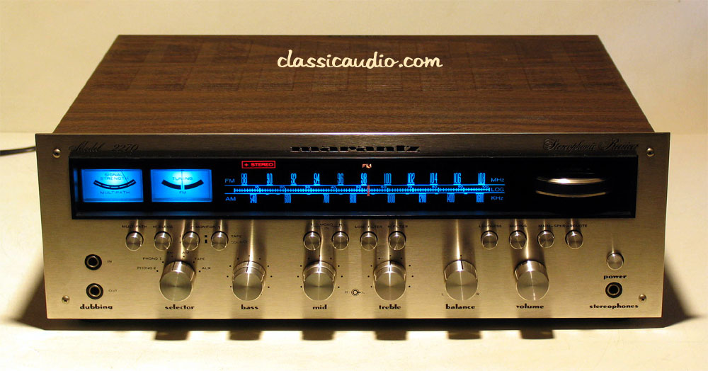
* A 70's era Marantz stereo
(http://www.classicaudio.com/forsale/mz/2270.jpg) which controls a TV/radio
tuner card or media player
* A real car dashboard, steering wheel and pedals wired for use with
driving simulators
* A vacuum tube (http://www.jvgavila.com/kwm2a_u2.jpg) or analog meter
(http://jenkins.com/jenkins/transformers/images/HORIZ.jpg) which responds to
system load, temperature, phase of the moon, etc.
* Robot control
* A broken audio mixer (whose controls still work), insides gutted, which
controls PC-based audio production software
* A mixer slider which controls the scroll bars on your windows
* Scrounged switches, knobs, dials, sliders, and pushbuttons which have
user-controllable functions (load software, logout, lock/unlock screen, etc.)
Almost all of the devices described here fall into just a few categories:
switches, potentiometers, and variable capacitors, and are all easy to connect
to a computer if you know how and have a few simple pieces of equipment.
The prototype Gadgetboard used an Atmel (http://www.atmel.com/) prototyping
board
(http://shop.kanda.com/index.php3?cs=1&bc=direct&bw=%2Fbrowse.php3%3Fpartno%3DNSTK300)
programmed to use a serial-based command line interface, so it behaved much
like our production board. Our production board's expanded capabilities would
have made these applications even easier. See some sample projects
(http://c3po.cs.byu.edu/~jason/uio/0thumbs.html): (.avi files are MJPEG/PCM)
* Controlling xmms with a car radio (.avi)
(http://c3po.cs.byu.edu/~jason/uio/xmms.avi).jpg
(http://c3po.cs.byu.edu/~jason/uio/controlsSM.jpg)
* Displaying system load with an analog meter(.avi)
(http://c3po.cs.byu.edu/~jason/uio/systemload.avi)
* Using the analog meter to show sound volume(.avi)
(http://c3po.cs.byu.edu/~jason/uio/vumeter.avi)
[edit]
Where can I get a Gadgetboard?
The file Gadgetboard1.0.tar.gz
(http://c3po.cs.byu.edu/~jason/Gadgetboard1.0.tar.gz) contains everything you
need to build your own board from scratch. Contact me, gadgets (at) lunkwill
[dot] org about pre-built boards.
As an alternative, you can buy a manufactured PCB (board) from me (much cheaper
than having your own manufactured), then order the parts from Digikey and
assemble and program the board yourself (soldering required, but it's
relatively easy soldering):
    * Download the tarball listed above.
    * Obtain a blank board
* Visit [1] (http://digikey.com) and create an account. Login, then select
"text file import". Upload the contents of the file "partslist.txt" from the
tarball. This creates an order of all the parts you need, which you can edit
before completing. The total should come to about $61 before S/H.
* When the parts arrive, use the circuit/atmelboard.png and
circuit/outputpage.png images as a guide to soldering the components in the
right places. Resistors and header pins can go in either way, but zener diodes,
capacitors, chips, etc. have to be put in the right direction. More detailed
instructions will be developed later.
    * On a Debian GNU/Linux system, as root:

# apt-get install gcc-avr avr-libc minicom
# chmod a+rw /dev/ttyS0

    * Then, in a nonprivileged account:

$ export AVRLIB=/path/to/avrlib/from/tarball
$ cd path/to/src/from/tarball
$ make
* When the board is complete, it's ready to program. Plug in a suitable
power source, such as a 12VDC 100mA (or higher current) wall wart. Install 4
jumpers on J101-J104. Then:
$ make wrfuses
$ make load
* Remove the jumpers and load minicom. Set minicom for /dev/ttyS0, and
38400 8N1. Reset the power for the board and you should see a welcome message
and prompt. Way to go!
--------------------
BYU Unix Users Group
http://uug.byu.edu/
The opinions expressed in this message are the responsibility of their
author. They are not endorsed by BYU, the BYU CS Department or BYU-UUG.
___________________________________________________________________
List Info: http://uug.byu.edu/cgi-bin/mailman/listinfo/uug-list