On 10/10/2016 5:14 PM, [email protected] wrote:
> OK all. I'm installing a 6m rotating beam and feeding it with LMR400. Would
> you
connect the LMR to the antenna and allow it to move with the rotation, or run a
short
length of something much more flexible between the antenna and LMR? I have my
concerns
that the solid heavy inner conductor of the LMR won't take much movement.
>
> Harlan
> K4HES
OM Harlan,
I'd take the advice of K2ASP, W6XU, K6DGW, KL7UW, K9YC and K3DJC.
I've got 30+ years in military and commercial 2-way radio ranging from just
below 40 MHz to over 10 GHz. In that time, I have designed, built, installed,
moved, repaired, tuned, modified and replaced over 700 antennas. ("antennae"
refer to insect appendages)
The counsel of those in the list above agrees with my education and experience
and is worthy of your consideration as they know what they are talking about.
73,
Tim Colbert K3HX
---------- Original Message ----------
From: [email protected]
To: [email protected]
Subject: Elecraft Digest, Vol 150, Issue 9
Date: Tue, 11 Oct 2016 10:13:50 -0400
Send Elecraft mailing list submissions to
[email protected]
To subscribe or unsubscribe via the World Wide Web, visit
http://mailman.qth.net/mailman/listinfo/elecraft
or, via email, send a message with subject or body 'help' to
[email protected]
You can reach the person managing the list at
[email protected]
When replying, please edit your Subject line so it is more specific
than "Re: Contents of Elecraft digest..."
Today's Topics:
1. PX-3 Spoken For (David Gow)
2. Re: Antenna Question (Clay Autery)
3. Re: Antenna Question (Phil Kane)
4. Re: Antenna Question (Josh Fiden)
5. Re: Antenna Question (Fred Jensen)
6. Re: K-pod SSB macro (Don Wilhelm)
7. Re: Antenna Question (Clay Autery)
8. Re: K-pod SSB macro (Bill Frantz)
9. Re: Antenna Question (Bob)
10. Re: Antenna Question (John Parker)
11. Re: Antenna Question (Josh Fiden)
12. Re: Antenna Question (Josh Fiden)
13. Re: Antenna Question (Bob)
14. Re: Antenna Question (Clay Autery)
15. K3S Time Display Bug (Bob Martin)
16. Re: Antenna Question (Mark E. Musick)
17. Re: Interlocking two K3 (Don Wilhelm)
18. Re: Interlocking two K3 (Edward R Cole)
19. Re: Antenna Question (Edward R Cole)
20. Re: Antenna Question (Vic Rosenthal)
21. Re: Antenna Question (Jim Brown)
22. [K3] KPA3A low Bias (Martin)
23. K3S with ACOM 1000 linear amp. (Alex Dokic)
24. Re: Antenna Question (Nr4c)
25. K3S with ACOM 1000 linear amp. (Martin)
26. I: K3S with ACOM 1000 linear amp. ([email protected])
27. Re: Antenna Question (Vic Rosenthal 4X6GP)
28. Re: Antenna Question (Charlie T, K3ICH)
29. Elecraft K3S wth Acom 1000 (Alex Dokic)
30. Re: Antenna Question ([email protected])
31. Fw: Re: Antenna Question ([email protected])
----------------------------------------------------------------------
Message: 1
Date: Mon, 10 Oct 2016 15:38:33 -0700
From: David Gow <[email protected]>
To: [email protected]
Subject: [Elecraft] PX-3 Spoken For
Message-ID:
<ca+1a67tc-g2cnyv4yrtagsj_t-jk4b71kt7_5vjq+atuapx...@mail.gmail.com>
Content-Type: text/plain; charset=UTF-8
The PX-3 I posted has been spoken for. Thanks for all the responses. If
it fall through I will contact all who responded in the order received.
73 Dave
W7VM
------------------------------
Message: 2
Date: Mon, 10 Oct 2016 17:44:35 -0500
From: Clay Autery <[email protected]>
To: [email protected]
Subject: Re: [Elecraft] Antenna Question
Message-ID: <[email protected]>
Content-Type: text/plain; charset=windows-1252
You'll get lots of suggestions, but I believe the use of a single
unbroken feedline from the antenna to the shack (when possible) trumps
the inconvenience of properly engineering an install that does NOT put
unnecessary repetitive bending moments on the line.
Do the research.... There's all kinds of info on how to create/route a
feedline for rotator use...
Most of the people I know with tall towers and big antennae use LMR-400
(or similar size) AS the "smaller jumper".
No reason NOT to use LMR-400 from the antenna to the station...
______________________
Clay Autery, KY5G
MONTAC Enterprises
(318) 518-1389
On 10/10/2016 5:14 PM, [email protected] wrote:
> OK all. I'm installing a 6m rotating beam and feeding it with LMR400. Would
> you connect the LMR to the antenna and allow it to move with the rotation, or
> run a short length of something much more flexible between the antenna and
> LMR? I have my concerns that the solid heavy inner conductor of the LMR won't
> take much movement.
>
> Harlan
> K4HES
>
> ______________________________________________________________
> Elecraft mailing list
> Home: http://mailman.qth.net/mailman/listinfo/elecraft
> Help: http://mailman.qth.net/mmfaq.htm
> Post: mailto:[email protected]
>
> This list hosted by: http://www.qsl.net
> Please help support this email list: http://www.qsl.net/donate.html
> Message delivered to [email protected]
------------------------------
Message: 3
Date: Mon, 10 Oct 2016 16:34:57 -0700
From: Phil Kane <[email protected]>
To: [email protected]
Subject: Re: [Elecraft] Antenna Question
Message-ID: <[email protected]>
Content-Type: text/plain; charset=utf-8
On 10/10/2016 3:14 PM, [email protected] wrote:
> Would you connect the LMR to the antenna and allow it to move with the
> rotation, or run a short length of something much more flexible between the
> antenna and LMR?
Commercial practice is to use a flexible jumper and "drip loop" between
the feedline and the antenna, even if the antenna is fixed solid to the
tower/mast. This relieves the stress on the antenna connector.
73 de K2ASP - Phil Kane
Elecraft K2/100 s/n 5402
>From a Clearing in the Silicon Forest
Beaverton (Washington County) Oregon
------------------------------
Message: 4
Date: Mon, 10 Oct 2016 16:49:07 -0700
From: Josh Fiden <[email protected]>
To: [email protected]
Subject: Re: [Elecraft] Antenna Question
Message-ID: <[email protected]>
Content-Type: text/plain; charset=windows-1252; format=flowed
With an unbroken feedline, a failure or antenna swap can require
soldering connectors up the tower. Not fun. If you're concerned about
the additional loss of a barrel connector at 50MHz, you should be using
feedline with lower loss than LMR400 up the tower. Wrap the barrel
connection with good quality 3m vinyl tape and paint over with
Scotchkote to keep water out.
YMMV!
73,
Josh W6XU
On 10/10/2016 3:44 PM, Clay Autery wrote:
> I believe the use of a single
> unbroken feedline from the antenna to the shack (when possible) trumps
> the inconvenience of properly engineering an install that does NOT put
> unnecessary repetitive bending moments on the line.
------------------------------
Message: 5
Date: Mon, 10 Oct 2016 17:00:24 -0700
From: Fred Jensen <[email protected]>
To: [email protected]
Subject: Re: [Elecraft] Antenna Question
Message-ID: <[email protected]>
Content-Type: text/plain; charset=windows-1252; format=flowed
As is military practice as well. If you really want to get picky, the
400 should come up to the connector [sealed of course] and supported on
the tower, and then the jumper forms the drip loop to prevent water
running down the coax from running over ... and eventually into ... the
connector.
I don't think I'd run 400 all the way to a rotating antenna.
73,
Fred K6DGW
Sparks NV USA
Washoe County DM09dn
On 10/10/2016 4:34 PM, Phil Kane wrote:
> On 10/10/2016 3:14 PM, [email protected] wrote:
>
>> Would you connect the LMR to the antenna and allow it to move with the
>> rotation, or run a short length of something much more flexible between the
>> antenna and LMR?
>
> Commercial practice is to use a flexible jumper and "drip loop" between
> the feedline and the antenna, even if the antenna is fixed solid to the
> tower/mast. This relieves the stress on the antenna connector.
>
> 73 de K2ASP - Phil Kane
> Elecraft K2/100 s/n 5402
------------------------------
Message: 6
Date: Mon, 10 Oct 2016 20:32:42 -0400
From: Don Wilhelm <[email protected]>
To: Peter Dougherty <[email protected]>, [email protected]
Subject: Re: [Elecraft] K-pod SSB macro
Message-ID: <[email protected]>
Content-Type: text/plain; charset=windows-1252; format=flowed
pjd,
No command that I know of, but let me offer a compromise being a
combination of the M1-M4 per band memories and the Macros that are fired
from the K-Pod.
The closest thing I can think of is to set up the M1-M4 memories for
each band. I use M1 for CW mode, M2 for data mode, and M3 for SSB mode
- M4 is unused in my case.
That will get you to a particular frequency in each band (but it will
not be the last used), but will set the mode as you have requested.
Once those are set up. you can use the K-pod buttons to send macros
which will "push those buttons". Yes, your macros will have to push the
M>V button and then the proper M1-M4 button. If your interest is in SSB
only, you will only use one of the K-Pod buttons. Each additional mode
will require another K-Pod button.
I do not use the K-Pod, but I do use the M1-M3 buttons as I have described.
My M1 thru M3 buttons send the frequency to somewhere mid-band in each
of the mode segments. It is easy to QSY from that point.
73,
Don W3FPR
On 10/10/2016 12:55 PM, Peter Dougherty wrote:
> Hi all,
> Just wondering if there's a command to select the last-used phone mode when
> creating macro sequences. I can do mode-up and mode-down, or direct-select
> USB or LSB, but not select either the default mode based on band or the
> last-used mode based on band (which for me are identical). If I'm operating
> in RTTY or CW and wish to QSY to an SSB split operation I'd like to be able
> to include a mode operator in the macro sequence, as I can for every other
> mode. (MD3; for CW, MD6; for RTTY, etc). But for SSB, since 3 bands are
> predominantly LSB and 5 are USB, I can't find a way to do this
> automatically. Is it possible?
>
> Thanks.
>
------------------------------
Message: 7
Date: Mon, 10 Oct 2016 19:39:48 -0500
From: Clay Autery <[email protected]>
To: [email protected]
Subject: Re: [Elecraft] Antenna Question
Message-ID: <[email protected]>
Content-Type: text/plain; charset=windows-1252
All things being equal... IF you are using LMR-400 as the main feedline,
there is NO REASON to use a different diameter at the rotator...
I was simply responding to what the OP said were the conditions... NOT
the "ideal"...
Bottom line... IF you engineer and install things properly, the fewer
breaks in the feedline, the better...
Fail to see why an antenna failure or swap would require soldering "up
the tower"... unless for some reason you change feedline to antenna
connector type.... not likely... or you compromised a connector
termination or failed to weather protect properly.... In either case,
your odds of doing one of those things increase with every additional
connector you add to the line.
BTW, using the -DB suffix (if available) for any Times cable will
radically reduce the chances of moisture ingress on the feedline...
______________________
Clay Autery, KY5G
MONTAC Enterprises
(318) 518-1389
On 10/10/2016 6:49 PM, Josh Fiden wrote:
> With an unbroken feedline, a failure or antenna swap can require
> soldering connectors up the tower. Not fun. If you're concerned about
> the additional loss of a barrel connector at 50MHz, you should be
> using feedline with lower loss than LMR400 up the tower. Wrap the
> barrel connection with good quality 3m vinyl tape and paint over with
> Scotchkote to keep water out.
>
> YMMV!
>
> 73,
> Josh W6XU
>
> On 10/10/2016 3:44 PM, Clay Autery wrote:
>> I believe the use of a single
>> unbroken feedline from the antenna to the shack (when possible) trumps
>> the inconvenience of properly engineering an install that does NOT put
>> unnecessary repetitive bending moments on the line.
>
------------------------------
Message: 8
Date: Mon, 10 Oct 2016 17:55:42 -0700
From: Bill Frantz <[email protected]>
To: [email protected]
Subject: Re: [Elecraft] K-pod SSB macro
Message-ID:
<r470Ps-10116i-0FA74062531C4103BDB1BCFD7F53E293@Williams-MacBook-Pro.local>
Content-Type: text/plain; charset=UTF-8; format=flowed
I use 2 "M buttons" for Data A and RTTY. Like you I use the
other two for CW and SSB.
Another hack that might work is to set the mode to CW and then
use a macro to "press" the mode up button to switch to whichever
of LSB and USB was last used.
73 Bill AE6JV
On 10/10/16 at 5:32 PM, [email protected] (Don Wilhelm) wrote:
>The closest thing I can think of is to set up the M1-M4
>memories for each band. I use M1 for CW mode, M2 for data
>mode, and M3 for SSB mode - M4 is unused in my case.
---------------------------------------------------------------------------
Bill Frantz | If you want total security, go to prison.
There you're
408-356-8506 | fed, clothed, given medical care and so on.
The only
www.pwpconsult.com | thing lacking is freedom. - Dwight D. Eisenhower
------------------------------
Message: 9
Date: Mon, 10 Oct 2016 21:21:14 -0400
From: Bob <[email protected]>
To: Josh Fiden <[email protected]>, Elecraft Reflector
<[email protected]>
Subject: Re: [Elecraft] Antenna Question
Message-ID: <[email protected]>
Content-Type: text/plain; charset="windows-1252"
------------------------------
Message: 10
Date: Tue, 11 Oct 2016 01:37:36 +0000 (UTC)
From: John Parker <[email protected]>
To: "[email protected]" <[email protected]>, Elecraft Reflector
<[email protected]>
Subject: Re: [Elecraft] Antenna Question
Message-ID: <[email protected]>
Content-Type: text/plain; charset=UTF-8
There is a stranded center conductor version of the LM400, do not remember what
the designation is. I plan to use some for the same reason, going around a
rotor to a HexBeam.
73, John WB4UHCK3 #2165
On Monday, October 10, 2016 6:16 PM, "[email protected]"
<[email protected]> wrote:
OK all. I'm installing a 6m rotating beam and feeding it with LMR400. Would
you connect the LMR to the antenna and allow it to move with the rotation, or
run a short length of something much more flexible between the antenna and LMR?
I have my concerns that the solid heavy inner conductor of the LMR won't take
much movement.
Harlan
K4HES
______________________________________________________________
Elecraft mailing list
Home: http://mailman.qth.net/mailman/listinfo/elecraft
Help: http://mailman.qth.net/mmfaq.htm
Post: mailto:[email protected]
This list hosted by: http://www.qsl.net
Please help support this email list: http://www.qsl.net/donate.html
Message delivered to [email protected]
------------------------------
Message: 11
Date: Mon, 10 Oct 2016 18:37:56 -0700
From: Josh Fiden <[email protected]>
To: [email protected]
Subject: Re: [Elecraft] Antenna Question
Message-ID: <[email protected]>
Content-Type: text/plain; charset=windows-1252; format=flowed
On 10/10/2016 5:39 PM, Clay Autery wrote:
> All things being equal... IF you are using LMR-400 as the main feedline,
> there is NO REASON to use a different diameter at the rotator...
The point was using a lower loss cable for the long run up the tower,
such as hardline, then flexible cable for the rotor/drip loop and short
distance to the antenna feedpoint. At VHF, this is typical.
> Fail to see why an antenna failure or swap would require soldering "up
> the tower"...
Failure is not necessarily the antenna. It could be the solid center
conductor fracture after being flexed too many times :)
If you swap antennas and it's a single run of cable, you have to
manipulate the antenna on the tower to access the feedpoint. Then, for
example, if you put up a longer boom yagi, the feedpoint will most
likely be further away from the tower and your existing feedline won't
reach.
73,
Josh W6XU
------------------------------
Message: 12
Date: Mon, 10 Oct 2016 18:42:43 -0700
From: Josh Fiden <[email protected]>
To: Elecraft Reflector <[email protected]>
Subject: Re: [Elecraft] Antenna Question
Message-ID: <[email protected]>
Content-Type: text/plain; charset=windows-1252; format=flowed
Completely agree. If access isn't a problem and the additional loss of
more flexible cable is tolerable, that's a great solution. I haven't
used Davis Bury-FLEX but heard very positive reports about it.
73,
Josh W6XU
On 10/10/2016 6:21 PM, Bob wrote:
>
> For sure a consideration. There never is a perfect solution all is
> a compromise. For me I wanted a single run because I see any extra
> connectors as a potential failure points. My Tower is crank
> up/tilt-over so not even as much of a repair or change issue.
>
> Nobody has mentioned it here but Times makes a LMR400 Ultraflex. A
> possible solution. Another cable I have been happy with is this:
>
> http://www.davisrf.com/buryflex.php
>
------------------------------
Message: 13
Date: Mon, 10 Oct 2016 21:48:31 -0400
From: Bob <[email protected]>
To: Elecraft Reflector <[email protected]>
Subject: Re: [Elecraft] Antenna Question
Message-ID: <[email protected]>
Content-Type: text/plain; charset=windows-1252; format=flowed
OOPS... Original left here in HTML not plain text. Don't know why. Elecraft
in address book is listed as plain text only
Sorry,
Bob
K2TK
-------- Forwarded Message --------
Subject: Re: [Elecraft] Antenna Question
Date: Mon, 10 Oct 2016 21:21:14 -0400
From: Bob <[email protected]>
To: Josh Fiden <[email protected]>, Elecraft Reflector
<[email protected]>
For sure a consideration. There never is a perfect solution all is a
compromise. For me I wanted a single run because I see any extra connectors
as a potential failure points. My Tower is crank up/tilt-over so not even as
much of a repair or change issue.
Nobody has mentioned it here but Times makes a LMR400 Ultraflex. A possible
solution. The slightly increased loss on 50MC maybe about equal to the extra
connector loss. Another cable I have been happy with is this:
http://www.davisrf.com/buryflex.php
A ham owned company that has been very responsive to requests. Of my 7 feeds
6
use it and no issues and a few pieces are getting close to 8 years old.
73,
Bob
K2TK ex KN2TKR (1956) & K2TKR
<http://www.davisrf.com/buryflex.php>
On 10/10/2016 7:49 PM, Josh Fiden wrote:
> With an unbroken feedline, a failure or antenna swap can require soldering
> connectors up the tower. Not fun. If you're concerned about the additional
> loss of a barrel connector at 50MHz, you should be using feedline with lower
> loss than LMR400 up the tower. Wrap the barrel connection with good quality
> 3m
> vinyl tape and paint over with Scotchkote to keep water out.
>
> YMMV!
>
> 73,
> Josh W6XU
>
> On 10/10/2016 3:44 PM, Clay Autery wrote:
>> I believe the use of a single
>> unbroken feedline from the antenna to the shack (when possible) trumps
>> the inconvenience of properly engineering an install that does NOT put
>> unnecessary repetitive bending moments on the line.
>
------------------------------
Message: 14
Date: Mon, 10 Oct 2016 21:17:09 -0500
From: Clay Autery <[email protected]>
To: [email protected]
Subject: Re: [Elecraft] Antenna Question
Message-ID: <[email protected]>
Content-Type: text/plain; charset=windows-1252
On 10/10/2016 8:37 PM, Josh Fiden wrote:
> On 10/10/2016 5:39 PM, Clay Autery wrote:
>> All things being equal... IF you are using LMR-400 as the main feedline,
>> there is NO REASON to use a different diameter at the rotator...
> The point was using a lower loss cable for the long run up the tower,
> such as hardline, then flexible cable for the rotor/drip loop and
> short distance to the antenna feedpoint. At VHF, this is typical.
Right... I'd use the best/lowest loss feedline I could afford/source,
too... and then use a smaller jumper... I was simply responding to the
OP who said he was using LMR 400.... and saying that LMR-400 CAN and IS
frequently used as that "jumper" for the rotator loop... or something
similarly sized in the .4-.5 inch range....
>> Fail to see why an antenna failure or swap would require soldering "up
>> the tower"...
> Failure is not necessarily the antenna. It could be the solid center
> conductor fracture after being flexed too many times :)
THAT would be the result of improper design/installation
>
> If you swap antennas and it's a single run of cable, you have to
> manipulate the antenna on the tower to access the feedpoint. Then, for
> example, if you put up a longer boom yagi, the feedpoint will most
> likely be further away from the tower and your existing feedline won't
> reach.
Point taken.... I'm not a big part swapper/upgrader... I build things
the best I can so I don't have to upgrade, so I didn't think of that...
This situation would likely not occur for me, as I said above... I
would likely NEVER use LMR-400 for a feedline run up a tower. I'd use
the biggest/best feedline I could source/afford.
______________________
Clay Autery, KY5G
MONTAC Enterprises
(318) 518-1389
------------------------------
Message: 15
Date: Mon, 10 Oct 2016 19:34:50 -0700
From: Bob Martin <[email protected]>
To: [email protected]
Subject: [Elecraft] K3S Time Display Bug
Message-ID: <[email protected]>
Content-Type: text/plain; charset=us-ascii
It turns out that at least on the K3S, if you stay on one frequency for a long
time, with the time showing in the VFO B area, that displayed time drifts
slower and slower, losing 8 to 10 seconds (or more) over an hour.
This isn't RTC drift -- the RTC is fine -- it's the way the display processor
keeps the time display in software. If you do a number of things such as
changing bands, changing modes, or just tapping the DISP key, the displayed
time is corrected to the RTC time.
This was reported as a bug, and verified, back in February.
While it's considered a medium priority, and it's more or less cosmetic, it's
still a source of irritation. It bugs me.
I was hoping it would be fixed in the recent betas. It's still present in the
recent September beta firmware release.
Any ideas on time frames for squashing this bug?
Love the radio, and trying to convince Santa that I deserve a P3...
73,
Bob K6RTM
------------------------------
Message: 16
Date: Tue, 11 Oct 2016 02:43:35 -0000
From: "Mark E. Musick" <[email protected]>
To: "'John Parker'" <[email protected]>, <[email protected]>,
"'Elecraft Reflector'" <[email protected]>
Subject: Re: [Elecraft] Antenna Question
Message-ID: <[email protected]>
Content-Type: text/plain; charset="us-ascii"
I use LMR400-FLEX for my rotor loops and have had no problems. It has been
up since 1999 or 2000. LMR400-FLEX is the designator for the stranded center
conductor version. I also have used Davis FLEX LMR400 equivalent and if I
remember correctly Davis-FLEX that is what is stamped on the feedline. The
difference between LMR400 solid center conductor and LMR400 FLEX stranded
center conductor has a loss of about .1 or .2db more at 50 MHz. Again if my
memory is correct.
Mark, WB9CIF
-----Original Message-----
From: Elecraft [mailto:[email protected]] On Behalf Of John
Parker
Sent: Tuesday, October 11, 2016 1:38 AM
To: [email protected]; Elecraft Reflector <[email protected]>
Subject: Re: [Elecraft] Antenna Question
There is a stranded center conductor version of the LM400, do not remember
what the designation is. I plan to use some for the same reason, going
around a rotor to a HexBeam.
73, John WB4UHCK3 #2165
On Monday, October 10, 2016 6:16 PM, "[email protected]"
<[email protected]> wrote:
OK all. I'm installing a 6m rotating beam and feeding it with LMR400. Would
you connect the LMR to the antenna and allow it to move with the rotation,
or run a short length of something much more flexible between the antenna
and LMR? I have my concerns that the solid heavy inner conductor of the LMR
won't take much movement.
Harlan
K4HES
______________________________________________________________
Elecraft mailing list
Home: http://mailman.qth.net/mailman/listinfo/elecraft
Help: http://mailman.qth.net/mmfaq.htm
Post: mailto:[email protected]
This list hosted by: http://www.qsl.net
Please help support this email list: http://www.qsl.net/donate.html Message
delivered to [email protected]
------------------------------
Message: 17
Date: Mon, 10 Oct 2016 22:51:48 -0400
From: Don Wilhelm <[email protected]>
To: irdixon+lists <[email protected]>, [email protected]
Subject: Re: [Elecraft] Interlocking two K3
Message-ID: <[email protected]>
Content-Type: text/plain; charset=windows-1252; format=flowed
The time that the lockout of both transmitter is quite short, in
milliseconds, so the solution to that problem is for the first operator
to recognize that condition is to stop and then start again.
It should not happen frequently.
73,
Don W3FPR
On 10/8/2016 12:59 PM, irdixon+lists wrote:
> Hi All
> I don't like re-inventing the wheel, so I'm looking for a design to copy!
> I'm looking for a circuit to interlock two K3 so they cannot transmit
> simultaneously. I am aware of the simple connection cross linking the
> PTT out and Inbibit input on the 15 pin connector. That does not meet
> our needs as when both try to transmit - both are inhibited !!
>
------------------------------
Message: 18
Date: Mon, 10 Oct 2016 20:50:07 -0800
From: Edward R Cole <[email protected]>
To: [email protected]
Subject: Re: [Elecraft] Interlocking two K3
Message-ID: <[email protected]>
Content-Type: text/plain; charset="us-ascii"; format=flowed
The simple fix is to move the 470-ohm resistors to be inserted
between pin-1 and Pin-7. The resistor is used to limit current draw
when pin-7 is grounded (inhibiting Tx). With pin-10 directly
connected to pin-7, pin-7 will go directly to low when pin-10 does.
If you want a little more insurance that current goes the correct
direction add a diode pointing toward pin-10 from pin-7.
I am using inhibit with my station sequencer (except with the
opposite logic: INH=HI):
http://www.kl7uw.com/TX-INHIBIT.htm
also added a little more band logic for use with transverters and
disables inhibit with HF.
73, Ed - KL7UW
-----------------
From: "Val" <[email protected]>
To: <[email protected]>
Subject: Re: [Elecraft] Interlocking two K3
Message-ID: <835760C8560A48D18E811EB243F91E3E@OFFICE>
Content-Type: text/plain; format=flowed; charset="iso-8859-1";
reply-type=original
Charlie, how this could work after there is no way the TX Inh inputs
to be pulled down?
73, Val LZ1VB
> Roger:
> Look at:
>
> http://www.kkn.net/~n6tv/SimpleElecraftK3SO2RLockoutCircuit.pdf
>
> I belive it's different than the one you described in your email.
> I've
> used this one successfully.
>
> 73 charlie, k1xx
73, Ed - KL7UW
http://www.kl7uw.com
"Kits made by KL7UW"
Dubus Mag business:
[email protected]
------------------------------
Message: 19
Date: Mon, 10 Oct 2016 20:54:31 -0800
From: Edward R Cole <[email protected]>
To: [email protected]
Subject: Re: [Elecraft] Antenna Question
Message-ID: <[email protected]>
Content-Type: text/plain; charset="us-ascii"; format=flowed
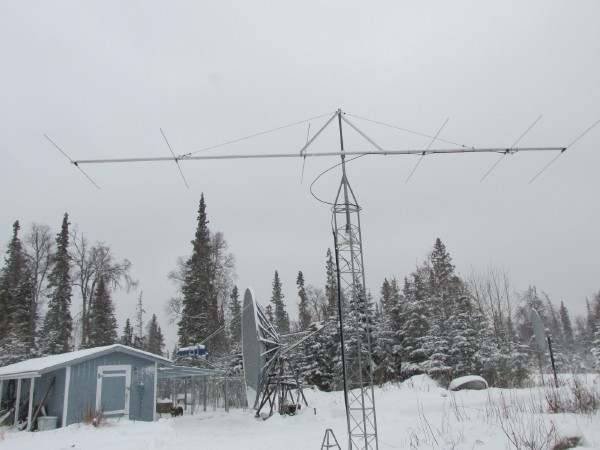
I do the same as Josh:
http://www.kl7uw.com/6m&Dish_Dec-2013_1.jpg
Multiple turns of LMR-400. That connects to 7/8-Heliax coming up the
tower leg.
73, Ed - KL7UW
From: Josh Fiden <[email protected]>
To: [email protected]
Subject: Re: [Elecraft] Antenna Question
Message-ID: <[email protected]>
Content-Type: text/plain; charset=windows-1252; format=flowed
LMR400 is really stiff. When I used it as a rotor loop, I made a couple
of hoops around rather than directly flexing the cable around the tower.
Not sure if that makes sense. In any case, doing it again I would
definitely use a more flexible jumper for the rotor loop running to the
antenna. In the shack I'm making jumpers from RG-214 which is very
flexible and would work great as a rotor loop as well.
73,
Josh W6XU
73, Ed - KL7UW
http://www.kl7uw.com
"Kits made by KL7UW"
Dubus Mag business:
[email protected]
------------------------------
Message: 20
Date: Tue, 11 Oct 2016 07:57:20 +0300
From: Vic Rosenthal <[email protected]>
To: [email protected]
Cc: Elecraft Reflector <[email protected]>
Subject: Re: [Elecraft] Antenna Question
Message-ID: <[email protected]>
Content-Type: text/plain; charset=us-ascii
One way to do it with a single piece of stiff coax is to place a standoff about
a foot long above and below the rotor. Then form the coax into a spiral of
several turns between the standoffs. Rotation will just tighten or loosen the
spiral and not stress the coax at all. The standoffs also take the weight of
the coax.
Vic 4X6GP
> On 11 Oct 2016, at 01:14, [email protected] wrote:
>
> OK all. I'm installing a 6m rotating beam and feeding it with LMR400. Would
> you connect the LMR to the antenna and allow it to move with the rotation, or
> run a short length of something much more flexible between the antenna and
> LMR? I have my concerns that the solid heavy inner conductor of the LMR won't
> take much movement.
>
> Harlan
> K4HES
>
> ______________________________________________________________
> Elecraft mailing list
> Home: http://mailman.qth.net/mailman/listinfo/elecraft
> Help: http://mailman.qth.net/mmfaq.htm
> Post: mailto:[email protected]
>
> This list hosted by: http://www.qsl.net
> Please help support this email list: http://www.qsl.net/donate.html
> Message delivered to [email protected]
------------------------------
Message: 21
Date: Tue, 11 Oct 2016 01:38:45 -0700
From: Jim Brown <[email protected]>
To: [email protected]
Subject: Re: [Elecraft] Antenna Question
Message-ID:
<[email protected]>
Content-Type: text/plain; charset=windows-1252; format=flowed
On Mon,10/10/2016 4:49 PM, Josh Fiden wrote:
> If you're concerned about the additional loss of a barrel connector at
> 50MHz, you should be using feedline with lower loss than LMR400 up the
> tower.
The loss in GOOD quality UHF connectors and barrels at 50 MHz is
negligible. There are urban legends (false, as usual) claiming that
every connector loses a dB. The grain of truth is that JUNK connectors
may introduce significant loss, but GOOD connectors and barrels do NOT.
"Good" means Amphenol 83-1SP for the PL-259s, and Amphenol or surplus
MIL-spec for the barrels.
Several years ago, I made up more than a dozen 100 ft cables using a
cable of somewhat better construction than LMR400 (Commscope 3227) for a
DX trip. The connectors were Amphenol 83-1SP that I soldered myself. To
test those cables, I spliced them together using Amphenol barrels and
measured the loss of about 1300 ft of cable up to 500 MHz using HP
generator and spectrum analyzer. The measured loss was LESS than the
manufacturer's spec. There were 27 83-1SPs and 13 barrels in line.
JUNK connectors are the shiny,unbranded stuff you see at ham flea
markets, and sold online and in ham magazines.
73, Jim K9YC
------------------------------
Message: 22
Date: Tue, 11 Oct 2016 11:22:55 +0200
From: Martin <[email protected]>
To: elecraft <[email protected]>
Subject: [Elecraft] [K3] KPA3A low Bias
Message-ID: <[email protected]>
Content-Type: text/plain; charset=utf-8; format=flowed
Elecrafters,
i built & maintain a new K3 for our local clubstation. We are preparing
for the upcoming Worked All Germany Contest and found the transmitted
signal being raspy, broad , just awful.
We talked to a few 'tech guys' on the bands and they all agreed that
this comes from a too low bias setting in the power amp.
With power levels below 12Watts all is good.
So i temporarily swapped the PA with a known working KPA3 (from my own
K3 ,ser >3000). The results were good.
I understand that the bias is factory set, OTOH there are 2 pots labeled
bias adjust . These pots are out of reach when KPA3A is operational.
How can i check for the bias and fix this problem myself?
The Contest is this weekend. All help appreciated.
--
Ohne CW ist es nur CB..
73, Martin DM4iM
------------------------------
Message: 23
Date: Tue, 11 Oct 2016 09:57:32 +0100
From: Alex Dokic <[email protected]>
To: [email protected]
Subject: [Elecraft] K3S with ACOM 1000 linear amp.
Message-ID: <[email protected]>
Content-Type: text/plain; charset=us-ascii
Hello all, I have a k3s and want to link it with my new acom 1000 amp. Looking
through both manuals i see the important info on controlling the drive power
with the power control on the k3 and not using ALC, also the TX delay time may
have to be increased a bit. I am not sure on the connection from the k3 to
acom. Will a Cable from the key out on the k3 to the key in on the acom work,
or do I need an interface. Any info will be appreciated on this subject. Alex
M0KVA
Sent from my iPhone
------------------------------
Message: 24
Date: Tue, 11 Oct 2016 06:52:29 -0400
From: Nr4c <[email protected]>
To: [email protected]
Cc: [email protected]
Subject: Re: [Elecraft] Antenna Question
Message-ID: <[email protected]>
Content-Type: text/plain; charset=us-ascii
Why use barrels? Doesn't Amphenol or Pastornack make a female UHF connector to
put on cable end. For this specific use, a custom built cable seems
appropriate.
Sent from my iPhone
...nr4c. bill
> On Oct 11, 2016, at 4:38 AM, Jim Brown <[email protected]> wrote:
>
>> On Mon,10/10/2016 4:49 PM, Josh Fiden wrote:
>> If you're concerned about the additional loss of a barrel connector at
>> 50MHz, you should be using feedline with lower loss than LMR400 up the tower.
>
> The loss in GOOD quality UHF connectors and barrels at 50 MHz is negligible.
> There are urban legends (false, as usual) claiming that every connector loses
> a dB. The grain of truth is that JUNK connectors may introduce significant
> loss, but GOOD connectors and barrels do NOT. "Good" means Amphenol 83-1SP
> for the PL-259s, and Amphenol or surplus MIL-spec for the barrels.
>
> Several years ago, I made up more than a dozen 100 ft cables using a cable of
> somewhat better construction than LMR400 (Commscope 3227) for a DX trip. The
> connectors were Amphenol 83-1SP that I soldered myself. To test those cables,
> I spliced them together using Amphenol barrels and measured the loss of about
> 1300 ft of cable up to 500 MHz using HP generator and spectrum analyzer. The
> measured loss was LESS than the manufacturer's spec. There were 27 83-1SPs
> and 13 barrels in line.
>
> JUNK connectors are the shiny,unbranded stuff you see at ham flea markets,
> and sold online and in ham magazines.
>
> 73, Jim K9YC
>
> ______________________________________________________________
> Elecraft mailing list
> Home: http://mailman.qth.net/mailman/listinfo/elecraft
> Help: http://mailman.qth.net/mmfaq.htm
> Post: mailto:[email protected]
>
> This list hosted by: http://www.qsl.net
> Please help support this email list: http://www.qsl.net/donate.html
> Message delivered to [email protected]
------------------------------
Message: 25
Date: Tue, 11 Oct 2016 14:13:16 +0200
From: Martin <[email protected]>
To: [email protected]
Subject: [Elecraft] K3S with ACOM 1000 linear amp.
Message-ID: <[email protected]>
Content-Type: text/plain; charset=utf-8; format=flowed
Alex,
no connections other than coax cable and a cable with cinch plugs both
ends are necessary.
Just set K3's power output to a level your Acom 1000 is satisfied with.
Make sure not to overdrive the Amp. Find the maximum drive level in the
manual of your Acom.
Your Amp will display an error message when drive level is set too high.
I use an Acom 1000 myself together with a K3. I never set the drive
level higher than the amp outputs about 100-200 Watts below maximum.
--
Ohne CW ist es nur CB..
73, Martin DM4iM
------------------------------
Message: 26
Date: Tue, 11 Oct 2016 14:47:52 +0200
From: [email protected]
To: Alex Dokic via Elecraft <[email protected]>
Subject: [Elecraft] I: K3S with ACOM 1000 linear amp.
Message-ID: <[email protected]>
Content-Type: text/plain; charset="utf-8"
Invio?eseguito?dallo?smartphone?BlackBerry?10.
? Messaggio originale ?
Da: [email protected]
Inviato: marted? 11 ottobre 2016 13:35
A: Alex Dokic via Elecraft; [email protected]
Oggetto: R: [Elecraft] K3S with ACOM 1000 linear amp.
I have a K3S connected to a new Acom 1000 from two months.?
I dont use alc, only the cable from ?the key out of K3?S to the Acom 1000 key
in.
You dont need any interface.
I work CW 90percent of my radio activity, always in QSK-full break in. I fixed
?qsk delay on K3S at 8mS, without any problem
?(Acom owner said me that Acom 1000 have no problem with a so fast switching).?
Faster switching doesnt anyway give problems or damage becouse Acom 1000
protections should stop amplifier and dont damage it, so he said.
But if you prefer you can opt for 10ms...
?Both K3S and Acom 1000 are great equipment.
I think the best.
Ian IK4EWX
Invio?eseguito?dallo?smartphone?BlackBerry?10.
? Messaggio originale ?
Da: Alex Dokic via Elecraft
Inviato: marted? 11 ottobre 2016 12:18
A: [email protected]
Rispondi a: Alex Dokic
Oggetto: [Elecraft] K3S with ACOM 1000 linear amp.
Hello all, I have a k3s and want to link it with my new acom 1000 amp. Looking
through both manuals i see the important info on controlling the drive power
with the power control on the k3 and not using ALC, also the TX delay time may
have to be increased a bit. I am not sure on the connection from the k3 to
acom. Will a Cable from the key out on the k3 to the key in on the acom work,
or do I need an interface. Any info will be appreciated on this subject. Alex
M0KVA
Sent from my iPhone
______________________________________________________________
Elecraft mailing list
Home: http://mailman.qth.net/mailman/listinfo/elecraft
Help: http://mailman.qth.net/mmfaq.htm
Post: mailto:[email protected]
This list hosted by: http://www.qsl.net
Please help support this email list: http://www.qsl.net/donate.html
Message delivered to [email protected]
------------------------------
Message: 27
Date: Tue, 11 Oct 2016 15:50:08 +0300
From: Vic Rosenthal 4X6GP <[email protected]>
To: [email protected]
Subject: Re: [Elecraft] Antenna Question
Message-ID: <[email protected]>
Content-Type: text/plain; charset=windows-1252; format=flowed
SOME 'junk' PL259s are fine. If there are problems with the threads you
will know right away. I have had some that are plated with something
that won't take solder, or which have plastic insulation that melts when
you solder the center pin. But again, you will know this right away.
SO239s and barrels may have contact tension problems that take awhile to
manifest themselves. And elbows and Ts can have internal issues (like
the famous elbows with little springs to join the two parts). For these,
only Amphenol or mil-spec will do.
Having said all this, just before I moved here, I ordered a bunch of
Amphenol connectors, including the PL259s.
73,
Vic, 4X6GP
Rehovot, Israel
Formerly K2VCO
http://www.qsl.net/k2vco/
On 11 Oct 2016 11:38, Jim Brown wrote:
> On Mon,10/10/2016 4:49 PM, Josh Fiden wrote:
>> If you're concerned about the additional loss of a barrel connector at
>> 50MHz, you should be using feedline with lower loss than LMR400 up the
>> tower.
>
> The loss in GOOD quality UHF connectors and barrels at 50 MHz is
> negligible. There are urban legends (false, as usual) claiming that
> every connector loses a dB. The grain of truth is that JUNK connectors
> may introduce significant loss, but GOOD connectors and barrels do NOT.
> "Good" means Amphenol 83-1SP for the PL-259s, and Amphenol or surplus
> MIL-spec for the barrels.
>
> Several years ago, I made up more than a dozen 100 ft cables using a
> cable of somewhat better construction than LMR400 (Commscope 3227) for a
> DX trip. The connectors were Amphenol 83-1SP that I soldered myself. To
> test those cables, I spliced them together using Amphenol barrels and
> measured the loss of about 1300 ft of cable up to 500 MHz using HP
> generator and spectrum analyzer. The measured loss was LESS than the
> manufacturer's spec. There were 27 83-1SPs and 13 barrels in line.
>
> JUNK connectors are the shiny,unbranded stuff you see at ham flea
> markets, and sold online and in ham magazines.
>
> 73, Jim K9YC
------------------------------
Message: 28
Date: Tue, 11 Oct 2016 09:29:19 -0400
From: "Charlie T, K3ICH" <[email protected]>
To: <[email protected]>
Subject: Re: [Elecraft] Antenna Question
Message-ID: <[email protected]>
Content-Type: text/plain; charset="us-ascii"
I'm curious as to exactly why a "junk" connector supposedly has so much more
loss than a "good" connector?
They're probably both (nickel, silver ???) plated brass with a dielectric
insulator usually Teflon, phenolic or ??
Is it the plating, the insulator, the fit of the threads, the
solder-ability, or what, that makes the lossy?
I can understand it if the dimensions are way off or they don't thread on
properly, but that should be obvious in the installation process.
Not trying to start a fight or insult anyone.
73, Charlie k3ICH
------------------------------
Message: 29
Date: Tue, 11 Oct 2016 14:54:41 +0100
From: Alex Dokic <[email protected]>
To: [email protected]
Subject: [Elecraft] Elecraft K3S wth Acom 1000
Message-ID: <[email protected]>
Content-Type: text/plain; charset=us-ascii
Hi guys, a big thank you to everyone has replied to my post, this is Ham Radio
spirit!. Thanks M0KVA Alex .73
Sent from my iPhone
------------------------------
Message: 30
Date: Tue, 11 Oct 2016 09:59:41 -0400
From: <[email protected]>
To: [email protected]
Subject: Re: [Elecraft] Antenna Question
Message-ID: <[email protected]>
Content-Type: text/plain; charset=us-ascii
a much better good connector that prople think
Bob K3DJC
On Tue, 11 Oct 2016 09:29:19 -0400 "Charlie T, K3ICH" <[email protected]>
writes:
> I'm curious as to exactly why a "junk" connector supposedly has so
> much more
> loss than a "good" connector?
>
------------------------------
Message: 31
Date: Tue, 11 Oct 2016 10:05:11 -0400
From: <[email protected]>
To: [email protected]
Subject: [Elecraft] Fw: Re: Antenna Question
Message-ID: <[email protected]>
Content-Type: text/plain; charset=us-ascii
50 Ohm Magic, UHF Connectors
TO: The Savvy Microwave Group
FROM: Dick, K2RIW.
RE: Coax Impedances, Losses, and the Maligning of UHF Connectors.
Coax Impedances, Losses, and the Maligning of UHF Connectors
by Dick Knadle, K2RIW, 31 May 2001.
Coax Impedance -- Concerning the possible choices of the impedance of a
coaxial transmission line, a great reference is "Microwave Transmission
Design Data", by Theodore Moreno, Dover Publications, 1948. On pages 64
through 69 he discusses four criteria for choosing a particular
impedance. The four choices displayed in the graph on page 64
demonstrates how non-critical (broad ranged) many of these impedances
are. Most of the following addresses air dielectric coaxial transmission
lines. Here are some interesting "Moreno" facts:
1. The maximum continuous power handling occurs at an impedance of 30
ohms.
2. The maximum breakdown voltage occurs at an impedance of 60 ohms.
3. The minimum insertion loss occurs at 77 ohms.
4. The maximum shorted line, resonant impedance occurs at 133 ohms.
5. Conductor losses (in dB's) are proportional to the square root of
frequency.
6. Dielectric loss (in dB) is linearly proportional to frequency. Hence,
at higher frequencies the dielectric losses become increasingly
important.
Cable Graphs -- We have all seen graphs of the insertion loss of our
favorite cables. They are usually displayed on Log-Log paper with the
horizontal axis being frequency, and the vertical axis being insertion
loss in dB per 100 feet (or 100 meters). The curious thing is that the
insertion loss graph appears as a sloping straight line, with some of the
cables displaying a slight upward hook at the highest recommended
frequency. Here is the explanation.
On Log-Log paper an exponential function appears as a straight line where
the slope is proportional to the exponent value. A square root function
has a exponent of 1/2. A linear function has an exponent of 1. On most of
the cables, only the conductor losses (exponent of 1/2) are significant
throughout much of the recommended frequency range. Thus, most of that
range is displayed with a slope of 1/2. The hook at the end represents
the upper frequency range where the dielectric losses are beginning to
kick in. Here the line is beginning to slide into a slope of 1.5, due to
the combined effects of the 1/2 slope (conductor losses), plus the 1.0
slope (dielectric losses).
Estimating Trick -- Knowing these facts allows you to make some
interesting mental approximations. Let's assume you know that your
favorite cable has an insertion loss of 1.0 dB per 100 feet at 144 MHz.
If your friend asks you what's the approximate loss at 432, here is what
you can do. Since you know that the cable is usable to at least 2 GHz,
you assume that conductor losses dominate throughout most of the 144 to
432 frequency region, and conductor loss is proportional to the square
root of frequency. 432 MHz versus 144 MHz is a 3:1 frequency ratio. The
square root of 3 is 1.73. Multiply the 144 MHz loss (1.0 dB) by the 1.73
factor, and you come up with a predicted approximation of 1.73 dB per 100
feet at 432 MHz. Because there will be a slight contribution due to
dielectric losses at this end of the cable's operating range you could
round your prediction up to 1.75 dB per 100 feet. Try this procedure on
the graphs of your favorite cables and you will be amazed how close the
approximation usually is.
Cut-Off Frequency -- As you go beyond the manufacturer's upper
recommended frequency, the cable is capable of acting like a round piece
of wave guide (WG). The presence of the center conductor adds a little
capacitive loading that slightly lowers the WG cut-off frequency. Moreno
recommends using this approximate equation for predicting the cut-off
wavelength:
Lambda = Pi * (a + b).
a = outer radius of the center conductor. b = inner radius of the outer
conductor. Pi = 3.1416 ...
In other words, the limiting wavelength is approximately equal to the
circumference at the arithmetic mean diameter.
Coaxial WG -- Now, don't let this limitation always scare you into
submission. The cable isn't going to explode if you use it above the
recommended frequency, it just gets a little tricky up there. The first
wave guide (WG) mode to consider is the TE11 circular mode. That's the
one used by the 10 GHz guys who are using 3/4 inch water pipe as a poor
man's wave guide -- it turns out to be a very high quality [low loss]
wave guide. In the TE11 WG mode the maximum E-field lines flow from the 6
o'clock position to the 12 o'clock position in the pipe (vertical
polarization is assumed). If your coax cable doesn't have any significant
bends in it, and the inner conductor is centered, it won't launch any
E-field (WG mode) at right angles to the center conductor. Your next
question is "what's a significant bend?" The microwaver's are going to
have to study this, but, my gut feel is that a bend radius of greater
than 1 foot is OK.
It is just a matter of time until some smart amateur intentionally
launches both propagation modes in a piece of coax in order to lower the
over-all insertion loss. It will require some careful tuning of the
launching structures at each end of the cable to insure that the two
modes end up co-phase at the top of the tower. This is because the phase
velocity of the WG mode is faster than the coaxial mode. This technique
can only be applied to a narrow band situation, or a set of narrow band
situations (like 5 GHz and 10 GHz).
UHF Connector Maligning -- There are many misinformed engineers and
amateurs who have been led to believe that a UHF connector is the worst
thing ever invented in the RF world -- due to it's lower internal
impedance. They believe that each UHF connector causes a 1/2 dB insertion
loss and a whole lot of VSWR at 432 MHz. I've heard quite a few amateurs
claim that their 432 MHz brick amplifier will now have 1 dB greater gain
since they just replaced the two chassis mounted UHF connectors with Type
N connectors. This "Old Wive's Tale" has been propagated for decades.
Everyone believes it. No one challenges it. Few people have ever make the
measurement.
A High Power "Calorimetry" Test -- Here is my observation. I took a 432
MHz Stripline Parallel Kilowatt Amplifier and applied 700 watts through a
UHF female and a UHF male connector, and then into my antenna feed line.
After 10 minutes of 700 watts throughput power the UHF connectors were
mildly warm. If I estimate that "mildly warm" represents a dissipation of
3 watts out of 700 watts, that's an estimated insertion loss of 0.019 dB
for the pair of connectors. You're about to ask, "how can this be, the
internal dimensions are approximately a 35 ohm impedance, it's got to
cause a 1.43:1 VSWR?" Well, it doesn't.
Very Little Total System VSWR -- The mated UHF connector has an internal
connector length of less than 0.9 inches. A free space wavelength at 432
MHz is 27.3 inches. The 0.9 inches represents a phase length of 11.9
degrees. If I plot this up on a Smith Chart (or use the mathematical
equivalent) I find the following. A 50 ohm antenna with an 11.9 degree
long section of 35 ohm line causes an input impedance of (47.9 -j7) ohms.
That's an input VSWR of 1.16:1, which gives a worse case
reflected-power-caused transmission loss of 0.024 dB. To me that's
insignificant. Now, I'll admit that at 10 GHz, where the wavelength is
1.1 inches, that 0.9 inch electrical length connector would be much
harder to tolerate.
Power Tolerance -- A Type N connector can tolerate low-duty pulses of
over 20 kilowatts without a voltage break down. However, steady state
power of more than 1 kW could cause the connector to fail from the RF
current overheating the center pin. Most connectors have a very similar
failure mechanism when steady state high RF power is applied. The UHF
connector has an oversized center pin that can more easily tolerate high
steady state RF currents. Moreno said that 30 ohms impedance maximizes
the power handling, and the UHF connector has an impedance of about 35
ohms.
Each EME'er who is using those expensive type SC connectors on his kW
amplifier could probably use UHF connectors for his indoor cable
attachments, if he desired to save money. The UHF connector has a larger
center pin than an SC connector, it might actually have a larger power
tolerance than the SC -- this will require testing. But, remember that
the Fluoroloy-H dielectric on the SC connector is designed to be a good
heat sync that cools the center pin.
It's User Friendly Assembly -- There are probably twice as many amateurs
who can do a good job of installing a UHF connector on an RF cable, as
compared to a Type N connector. The proper installation and WX proofing
of a Type N connector requires considerable finesse and experience. It's
almost an art form.
UHF Connector Faults -- There are two major faults I can find with a UHF
connector when it is being used on 432 and below: (1) the lack of weather
proofing; (2) the lack of outer conductor finger contactors. With a
proper tape wrapping job, I believe the weather proofing can be
accommodated. However, the user must be sure that the internal "teeth"
are properly seated, and that the outer nut is kept tight; otherwise the
outer conductor can develop a considerable growth in electrical length,
with the associated "scratch contacting" noise. For this reason the
connector is probably inappropriate for a high vibration environment,
unless an auxiliary nut-retaining mechanism is employed.
So, maybe it's time we stop saying such bad things about the
poor-orphaned UHF connector. For our purposes, it doesn't deserve all
that flack. Properly used by a savvy engineer, who understands the
idiosyncracies, it can give you a lot of bang for the dollar. It's been
around for 60 years, that's no coincidence.
I welcome alternate opinions on all of the above. Please feel free to
correct the mistakes.
73 es Good VHF/UHF/SHF DX,
Dick, k2RIW.
Grid: FN30HT84DC27.
APPLICATION NOTES:
1. UHF Connector VSWR at 432 MHz
A 15 db return loss from a UHF connector that's being used at 432 MHz is
quite good in many circumstances. That return loss (a 1.43:1 VSWR) only
causes an insertion loss of 0.14 dB (before correction, such as re-tuning
the transmitter). On the transmitter side of an EME system, you'll never
know it's there.
But, if there was a 15 dB return loss caused by a connector that's in
front of a well tuned LNA, that is significant. It could make a
considerable difference to the system's Noise Figure, if the operator did
not apply VSWR corrective action -- such as tuning the LNA for best Noise
Figure performance while it is connected to the real system.
However, I suspect that very few of the currently operation EME antenna
systems have a return loss of better than 15 dB -- particularly not
during rain and snow. Therefore, that savvy EME operater has had to apply
corrective action to the total antenna system, if he wants full
performance of his LNA. If the UHF connector is part of that antenna
system, it will get lumped together within that corrective procedure.
Thus, that connector 15 dB return loss could be very tolerable to a
well-informed operator.
2. More 50 Ohm Magic, UHF Connectors
Introduction -- In various responses to my 31 May 2001 treatment of UHF
connectors, cogent comments were made that I wish to address, and add to.
Connector Brands -- Since the UHF connector doesn't seem to be protected
by a MIL Specification, there is a wide variation in the quality and
mechanical performance of the connectors that are available on the world
wide market. The buyer must be wary. I hope that a savvy amateur will
create a web site list that will inform us of the UHF connector brand
names, and sources, that are worthy of our hard-earned money. Lloyd,
N5GDB, and Lloyd, NE8I both strongly recommend the silver plated or gold
plated versions, particularly with respect to solderability and
connection integrity.
Installation -- I probably was too hasty when I stated that twice as many
amateurs/engineers can properly install a UHF connector versus a type N
connector. An experienced RF maven (one who has a "feel" for the way RF
flows) can almost always suggest an improvement in the connector
installation procedure -- so that the lowest VSWR, least loss, best
mechanical strength, best longevity, and best weather proofing are
realized.
Most of my outdoor equipment uses type N connectors, with BNC's most used
indoors, and SMA's used within enclosures. For the few UHF connectors
that I use, here is my favorite connector installation method.
(1) After properly cutting back the braid and dielectric, I next tin the
braid (and center conductor) with as little solder as possible, that will
still coat the strands. Since the end of the cable is completely open to
air at this point, the amount of melting of the polyethylene dielectric
is minimized.
(2) I slip the nut onto the cable and then screw on the connector body.
The tinned braid causes extra resistance, and a strong pair of pliers are
definitely required.
(3) Assuming that I've chosen a connector brand that readily accepts
solder, the process of tack-soldering through the 4 holes requires very
little heating time, when using a large-enough, hot-enough, soldering
iron. Thus very little further melting of the polyethylene dielectric
takes place, and the complete braid is essentially bonded to the
connector body.
(4) Clean off as much solder from the tip of the iron as possible, and
heat up the side of the center pin, while applying solder down the front
hole. Try to keep solder off the side of the center pin. If need be, wipe
off any excess while it is hot. Excess solder left on the outside of
connector center pin will interfere with the proper mating with the
female connector.
A further benefit of the braid tinning process is that the strands of the
braid don't become scattered, spread, and folded back during the process
of screwing on the connector body. Thus, full braid strength, and
electrical bonding is assured by this process.
I suspect that other experts have further improvements on this process,
and I welcome their comments.
Crimp Connectors -- For indoor, non-critical applications I believe that
crimp connectors can be very expedient and handy. However, the crimping
process has a number of characteristics that bother me:
(A) True UHF Frequency VSWR -- For many crimp connector designs the outer
braid is crimped quite far back from the end of the cable. This creates
an outer connector choke assembly that makes the outer conductor longer
than the center conductor.
(B) Salt Spray Survival -- My previous salt mine (the former AIL System
Inc., now EDO-Electronic Systems Group) performed a number of salt spray
tests a few years ago on crimp-connected semi-rigid cables. The results
were not encouraging. In a number of the cables the UHF or SHF VSWR
changed considerably after a few cycles of the salt spray exposure. It is
hard to beat the RF bonding that a solder joint creates.
(C) Ultimate Shielding Requirement -- Arguably, the most critical
requirement for an indoor connector is that of the jumper cables on a
repeater's duplexing filter. In this application you desire the connector
to provide 110 dB of shielding integrity (if you can get it). I
personally have experienced repeaters that would develop "scratchy
interference" and RCVR desensitization as the type N crimp connected
jumpers were manually moved. Lloyd, NE8I also mentioned these problems
concerning silver plating. On the two occasions that I experienced this,
the problem was cured when the jumpers were replaced with well-installed
conventional type N connectors. I have been told of desperate repeater
owners who used conventional type N connectors, but modified them by
soldering the internal collet assembly to the cable braid before
assembling the connector, as a way of avoiding any oxidation-caused
scratchy braid connections.
(D) Weather Proofing the Crimp -- In a conventional type N connector, the
portion that consists of the compression bond of the braid and the
internal collet is all contained within the weather-proof portion of the
connector. However, in most crimp-type connectors, the crimped portion of
the cable's outer conductor is exposed to the weather. This suggests that
the crimped joint is subject to corrosion, and a subsequent poor
connection. Most of us will tape and shrink-wrap our outdoor type N
connectors as a "belt and suspenders" approach to secondary weather
proofing. In the case of a crimped connector, our weather proofing of the
outer braid is a primary protection requirement.
My (Crimp) Conclusion -- If we do a really good job of installing a
connector on an outdoor coaxial cable, we are likely to use that cable
for 10 to 15 years. A crimp connector is capable of saving you a
considerable amount of time during the initial installation. However, if
the crimp connector gives you trouble within the first few years of
service (that's what the salt spray tests suggest), than the time saving
during the installation of a crimp connector might really be a false
economy. I'm willing to spend an extra 10 minutes installing a connector,
if it is likely to give me over 10 years of service.
Here is my challenge. Does anyone know of a well documented set of salt
spray tests that were performed on various stiles of RF coaxial cable
crimp connectors? A salt spray test is a beautiful way of artificially
putting 10 years of aging into a cable assembly within a week. Many of us
live within a hundred miles of a sea shore, and this characteristic is
important to us. I'll admit that the Microwavers who live in the Mojave
Desert may not have this particular problem to worry about.
Mismatch -- Leonard, N3NGE spoke of the difficulty of sweeping a cable
system that has a high return loss connector at the beginning. Jerry,
K0CQ suggested that the problem can be overcome with a Time Domain
Reflectometer (TDR), and it will even display the water that is within a
section of the cable.
I've spent a few years of my life using TDR's and I love'em. They can
make RF measurements that will amaze you. However, they are expensive,
rare on the surplus market, and few colleges even mention this wonderful
instrument. That's unfortunate. A really good TDR will allow you to
inspect the integrity of your transmission line system at possibly every
1/8 inch at a time, and it will "look through" that poor connector that's
at the beginning of the cable. There are TDR "De-Embedding Techniques"
that will allow you to inspect portions of your cable that are surrounded
by some pretty significant mismatches.
There is a solution for us amateurs, it's called the Steinhelfer
Technique. If you sweep the cable, and stop at say 1,024 separate
frequencies, and measure the amplitude, and phase of the reflected power,
you now have a data set that can do magic. Apply this data set to a
computer program that performs a type of Fourier Transform, and it will
simulate a TDR that is far above the performance of the one that you
could afford.
We have all seen those fairly inexpensive hand held VSWR Sweeper-Plotter
machines. Add a phase measurement capability, and an RS-232 port to that
machine, and you're almost there. That modified hand held device will
gather the raw data, and a PC could process the data and make up the TDR
plots. A VSWR plotter that sweeps 1 to 1,000 MHz could give you the
capability of resolving what's going on in your transmission line system
every 6 inches. For most of us, that's good enough to locate a faulty
section. Sweep the data gatherer from 1 to 2,000 MHz, and you will
resolve every 3 inches, etc. It's about time that somebody offers this as
a new RF toy for our pleasure.
I'll admit that the Steinhelfer technique involves some fairly heavy
mathematics. But, it can be taken in stages, and you could share the
responsibility. Just assemble an RF maven, a mathematician, and a
Computer Science major, and point them in the right direction. This would
make a fantastic Senior Project for a group of engineering students.
Later, it might even make them rich. For those who wish to study this
further, see the following references:
(1) HP Application Note 62, "Time Domain Reflectometry", 1964.
(2) HP Application Note 67, "Cable Testing with Time Domain
Reflectometry", October 1965.
(3) HP Application Note 75, "Selected Articles on Time Domain
Reflectometry Applications", March 1966.
(4) Harry M. Crimson, "TDM: An Alternate Approach to Microwave
Measurements", Microwaves, December 1975.
(5) M. Hines and H. Steinhelfer, Time Domain Oscillographic Network
Analysis", IEEE MTT March 1974, pp. 276-282.
(6) P.I. Somlo, "The Locating Reflectometer", IEEE MTT, February 1972,
pp. 105-112.
(7) H.E. Steinhelfer, Sr., "De-embedding the Capacitance of a Resonant
Circuit Using Time Domain Reversal and Subtraction", IEEE MTT Int.
Microwave Symp. Digest, 1982, pp. 354-356.
(8) H.E. Steinhelfer, "Discussing the De-Embedding Techniques Using Time
Domain Analysis", IEEE Proceedings, January 1986.
(9) D.W. Hess and Victor Farr, "Time Gating of Antenna Measurements",
Microwave Journal, January 1989.
(10) D.L. Holloway, "The Comparison Reflectometer", IEEE MTT, April 1967,
pp. 250-259.
I'm looking forward to using this new RF Toy, so don't you guys
disappoints me now!
I hope this makes you feel a little more comfortable about UHF
connectors; they are really not as poor as some think. Please feel free
to correct the mistakes.
73 es Good VHF/UHF/SHF DX,
Dick K2RIW.
Grid FN30HT84DC27
[HOME] [NETS] [CALENDAR] [REFLECTOR] [CONTACT US] [REGISTER] [TECH FORUM]
[RELATED SITES] [PROPAGATION] [THE BANDS] [RMG APPLICATION]
go to the top
--------- Forwarded message ----------
From: <[email protected]>
To: [email protected]
Date: Tue, 11 Oct 2016 09:59:41 -0400
Subject: Re: [Elecraft] Antenna Question
Message-ID: <[email protected]>
a much better good connector that prople think
Bob K3DJC
On Tue, 11 Oct 2016 09:29:19 -0400 "Charlie T, K3ICH" <[email protected]>
writes:
> I'm curious as to exactly why a "junk" connector supposedly has so
> much more
> loss than a "good" connector?
>
______________________________________________________________
Elecraft mailing list
Home: http://mailman.qth.net/mailman/listinfo/elecraft
Help: http://mailman.qth.net/mmfaq.htm
Post: mailto:[email protected]
This list hosted by: http://www.qsl.net
Please help support this email list: http://www.qsl.net/donate.html
Message delivered to [email protected]
------------------------------
Subject: Digest Footer
_______________________________________________
Elecraft mailing list
Post to: [email protected]
http://mailman.qth.net/mailman/listinfo/elecraft
You must be a subscriber to post.
Elecraft web page: http://www.elecraft.com
------------------------------
End of Elecraft Digest, Vol 150, Issue 9
****************************************
______________________________________________________________
Elecraft mailing list
Home: http://mailman.qth.net/mailman/listinfo/elecraft
Help: http://mailman.qth.net/mmfaq.htm
Post: mailto:[email protected]
This list hosted by: http://www.qsl.net
Please help support this email list: http://www.qsl.net/donate.html
Message delivered to [email protected]