On Wednesday, December 29, 2021 8:31:49 PM EST John Dammeyer wrote:
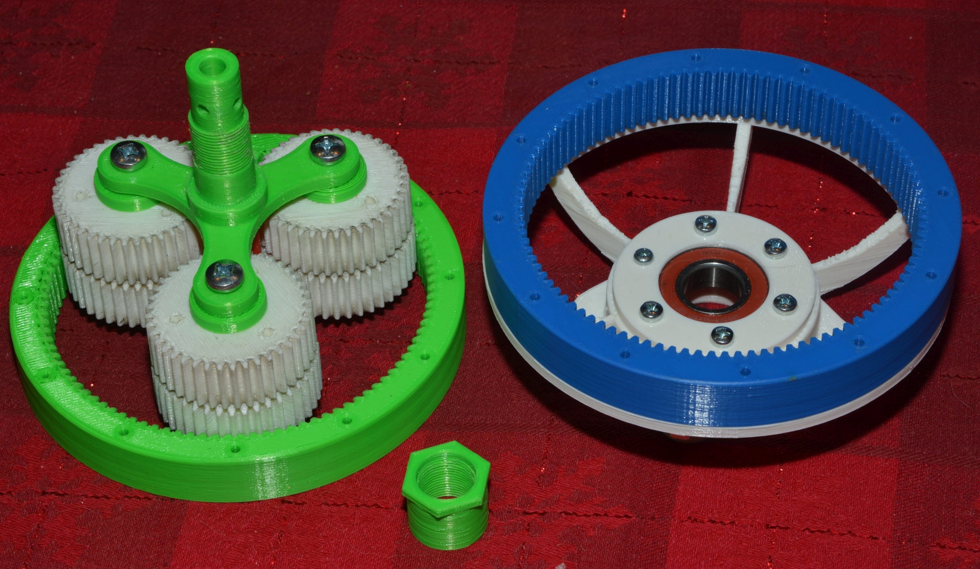
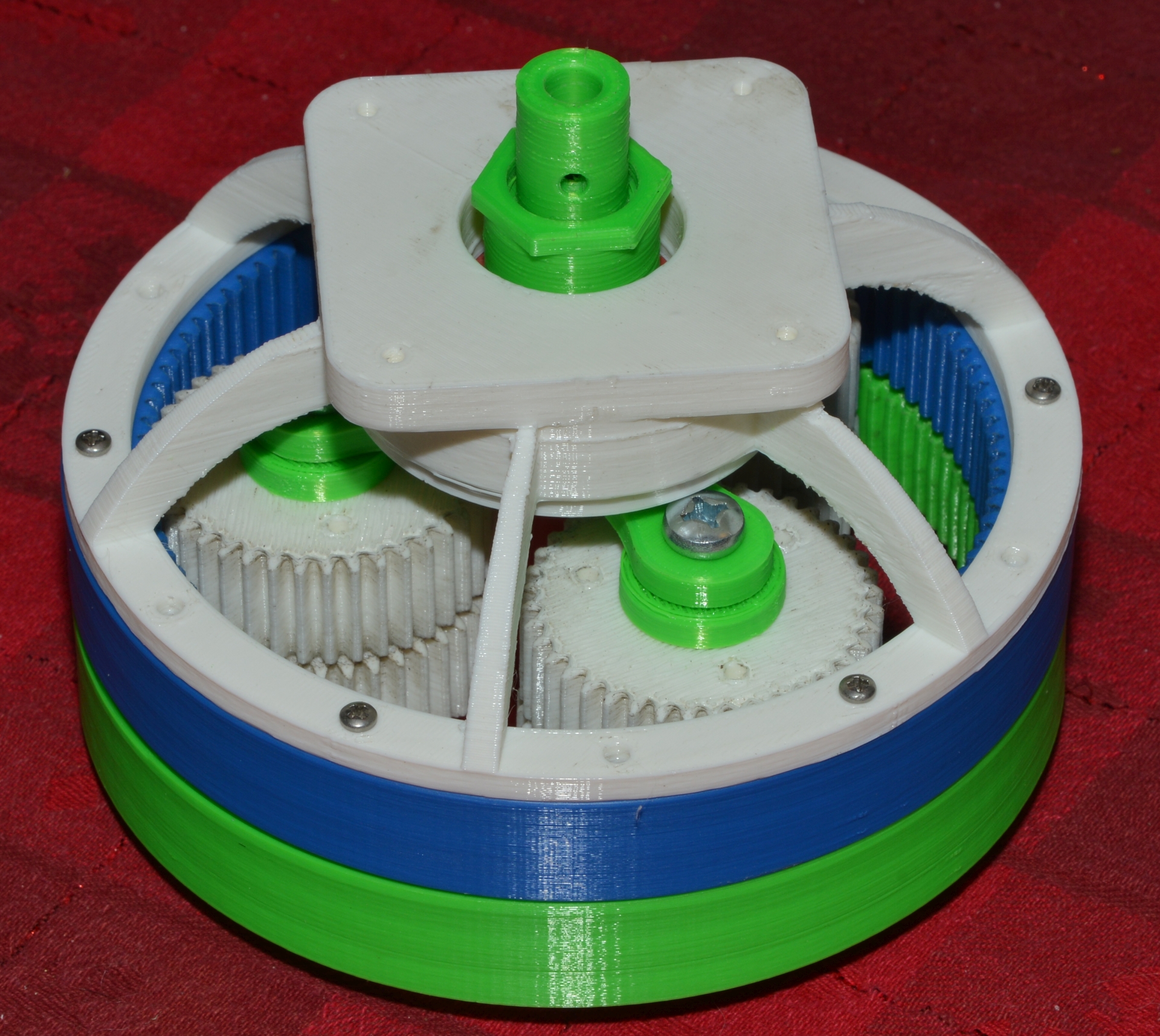
> Small progress report on Todd's version of the harmonic drive.
>
> I added a back mount that holds a 19x40x12 bearing. A cap to hold the
> bearing in place. Then a new drive arm sized to 19mm and a 19x1.25mm
> thread along with a nut. The end of the drive shaft has an 8mm hole for
> the stepper motors that arrived last week. Will likely require a metal
> collar around that part with threaded holes to clamp the flats on the
> motor shaft. The plastic just isn't strong enough to hold these types of
> threads.
Yes is is John. lay and gently clamp the motor on the mill table, and use a
CBN wheel intended for a valve grinder, a turn the flat as level as you can,
power it up with the driver so its locked, and sweep slowly back and forth
across the flat until you've removed another mm. Size the rest of the 8mm
hole in the printout by positioning a square shape so as to use up that
wider flat with plastic. I am assembling a much stronger version of the
drive I've had running for a life test of the design since the first week of
September. And that's one thing I didn't change. The 8mm hole for that shaft
is sized to be a deadblow hammer fit on that motor shaft and with the bigger
flat, it has strength to spare. I can drive it onto the shaft of a 3nm
motor, grab it with vice grips and stall the motor. Its normal driver is a
1mn motor which also has the 8mm shaft. Go easy on the rate of removal as
the shaft steel is soft and will smear if you push the rate too high.
Might not work in the much more brittle pla, but in petg, piece of cake.
Currently I am using a printed eliptical armature, with 4 printed ball
bearings 6mm wide riding on that 24mm long armature, fitted to a loose belt
that's not really loose as its a drive fit over the stack of bearings, tite
enough the outer races do not slip on the inside of the belt. And its
currently set for a 50/1 ratio. I am currently fine tuning some sizes by the
last .05mm here and there. I just found it possible to split the outer races
in two trying to dis it to lube for the final assembly and made the armature
.3mm smaller so I could give that material to the outer race, making it a
bit stronger. And I am doing it in OpenSCAD, the AppImage: OpenSCAD version
2021.12.12.ai9755 (git b5aba496f) downloaded from their site about 3 weeks
back. My code, as it exists right now, is attached. It's messy, about 80% my
code, but some borrowed from thingyverse.
> http://www.autoartisans.com/harmonicdrive/BearingDriveShaft-1.jpg
> http://www.autoartisans.com/harmonicdrive/BearingDriveShaft-2.jpg
> http://www.autoartisans.com/harmonicdrive/BearingDriveShaft-3.jpg
>
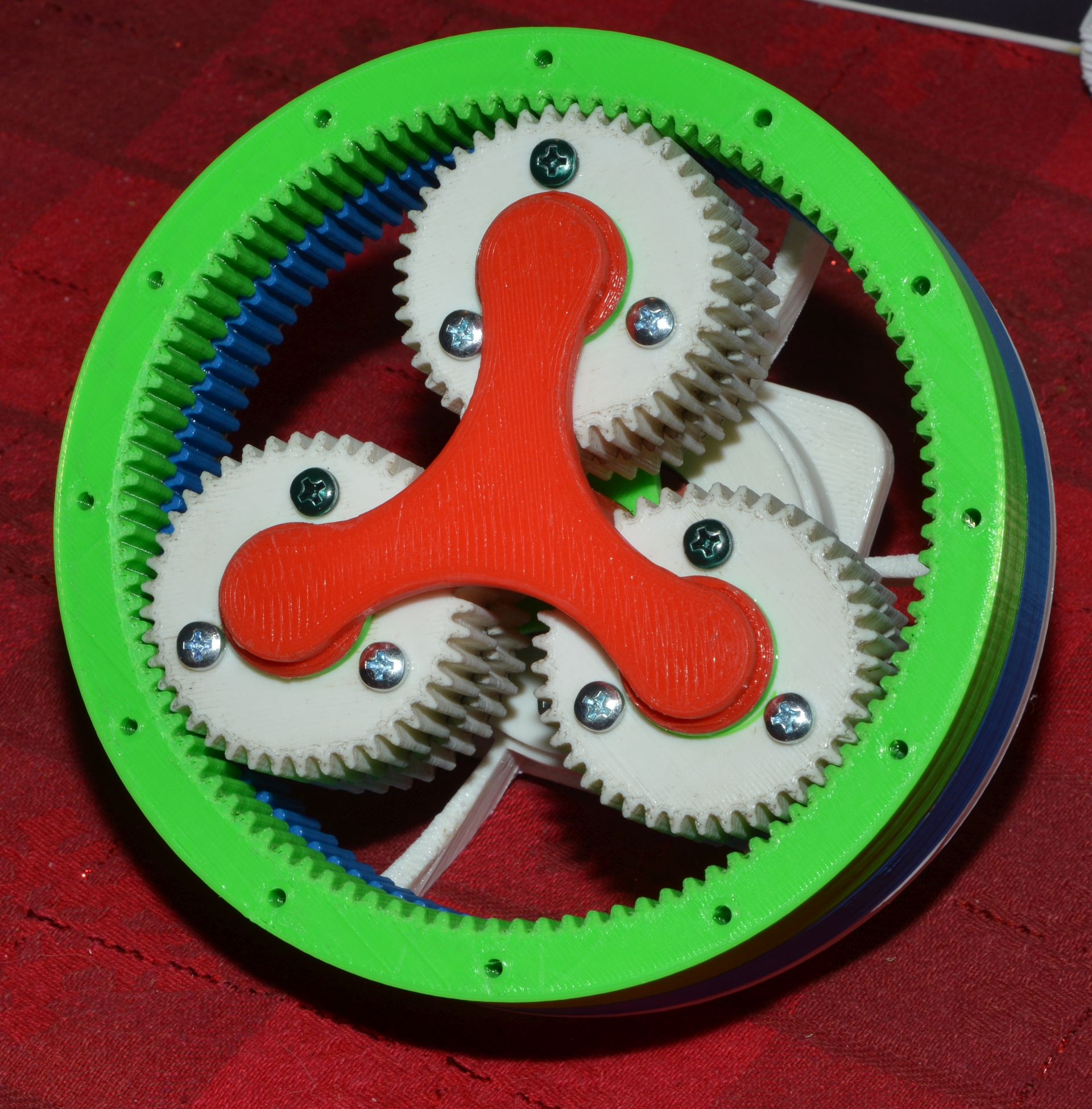
> Now to contain the green output gear. Here's one idea. I have a bag of
> 5.5mm steel balls meant for keeping model paint mixed. With 80 of them
> held in place by the bearing spacer (which I would probably make out of
> metal for this project) it should theoretically capture the gear and
> reference it to the mounted frame. A dual row of balls might be better.
>
> http://www.autoartisans.com/harmonicdrive/BearingPath.jpg
> http://www.autoartisans.com/harmonicdrive/BearingSpacer.jpg
> http://www.autoartisans.com/harmonicdrive/MountFrame.jpg
>
> Commercial units look like they use rollers set at angles but even a 32mm
> one from aliexpress is over $200.
Which is precisely why I'm using bb's. they aren't as precise as regular
bearings but then printed plastic is a bit lumpy too. Fit then a bit tight,
stuff full of bb's, roll it on the keyboard tray with a high loading until
the knobs in the plastic are mashed down and it turns easy. The whole idea
is if you break it, you can print another for $15 in petg and bb's plus the
$1.70 bearing in the far end of the armature. And even that is probably
optional. With or without supports, the end of the extra bearing hole in the
armature is messy.
> Probably the next best step to create something like this is to down size
> it to brass or steel gears small enough to fit into a much lower cost set
> of bearings. The key with this system will be the bearings.
>
> Anyway, other than printing a conversion base for motor to bearing
> assembly I'm not sure this warrants further work unless I can come up
> with an inexpensive method to contain the front gear. Suggestions, as
> always are welcome.
>
> John
>
>
>
>
> _______________________________________________
> Emc-users mailing list
> [email protected]
> https://lists.sourceforge.net/lists/listinfo/emc-users
> .
Cheers, Gene Heskett.
--
"There are four boxes to be used in defense of liberty:
soap, ballot, jury, and ammo. Please use in that order."
-Ed Howdershelt (Author, 1940)
If we desire respect for the law, we must first make the law respectable.
- Louis D. Brandeis
Genes Web page <http://geneslinuxbox.net:6309/gene>
// an attempt to make a 30/1 harmonic driver for my new smaller drive
// get data from prev. files.
// now, starting 12/22/2021, being made longer and stronger with 50/1
// ratio.
// for "mode" see line 589 1=build houseing,2=build spacer, 3= new armature,
// 4=armature bearings, 5=innerspline, 6=outcup, 7=60 tooth outer,
// 8=62 tooth outer. 9=timing pulley for output belt
// this is intended to be fitted to the A drive supplied with a 4 axis
// 6040 milling machine which due to low gear ratio, doesn't have the cajones
// to hold position. Not in this file, I've made a timing pulley that drives
// over the one
// supplied and replaces the huge belt with a 60 tooth for gt3 belt, with
// a longer offset to align with this drives output pulley.
// And I am in the process of making it for a direct on the motor mount
// whereas the original idea was to mount it on the back face of the
// mount which on the targetted A drive is 1/2" or 12mm thick. However,
// mounting it directly on the motor will put the end of the motor shaft
// into the middle of the output sprocket. Since the motor shaft is an
// 8mm modified dflat, a 10mm hole is now cut thru the bore of the output
// sprocket. In that event, the armature must lose its extended hub but that
// is yet to be done. It needs all the reinforcement it can get. Stay tuned.
hubsizeR=19.5; // it fits, quit diddling
IDofspl=67.05;
splsocht=6.00;
ODofCup=(IDofspl+splsocht*2.5);
sink=.745;// jack up bolt head countersink to top of 3.1 mm thick disk
sht=1.513;// height of countersink+noise in preview fudge
$fn=360;// make circles with 1 degree flats
reghole=38.3;// motor registration hole + printer undersize fudge, exact!
nemahole=(47.2/2); // one side of square pattern, 47.1 is official target,
ddht=3.1;//input panel with nema 23 bolt pattern
ddia=5.1;//5mm bolt clearance
//spacer ring height
spcringh =12;//could be 6.3
//spacer ring height1
spcringh1=6;//vertical offset
//spacer ring diameter 1 ID of housing wrapper
spcringd1=82.37;// outside of ring, id of surround band
//spacer ring diameter 2
spcringd2=67.9;// inside of spacer ring, press fit on spline od
//housing wrapper height
wrapperh=32;//surround band height.
//globals for keys
t1=spcringd1;
t2=(spcringd2+.1);
y=(spcringh*.5 + .1);
z1=4.2;// key sizes, will need tweaked to fit well, probably by .2 + & -
z2=3.8;
z3=2.3;
z4=1.8;
// globals for output timing pulley
toothType=1;
toothWidth = 1.14; // Teeth of PULLEY, that is. Larger=tighter fit of teeth.
// make motor faceing disk
module disk()
{
    translate([0,0,splsocht/4]) // set z bottom at 0
    difference()
    {
        cylinder(h=splsocht/2,d=spcringd1,center=true);
        cylinder(h=splsocht/1.5,d=reghole,center=true);// make registration
       // hole in center
        translate([nemahole,nemahole,0])cylinder(h=ddht,d=ddia,center=true);
        translate([-nemahole,nemahole,0])cylinder(h=ddht,d=ddia,center=true);
        translate([-nemahole,-nemahole,0])cylinder(h=ddht,d=ddia,center=true);
        translate([nemahole,-nemahole,0])cylinder(h=ddht,d=ddia,center=true);
// Now set flat head countersinks at 45 dgree angle so screw head is buried
        translate([nemahole,nemahole,sink])cylinder(h=sht,d1=ddia,d2=10.10,center=true);
        translate([-nemahole,nemahole,sink])cylinder(h=sht,d1=ddia,d2=10.10,center=true);
        translate([-nemahole,-nemahole,sink])cylinder(h=sht,d1=ddia,d2=10.10,center=true);
        translate([nemahole,-nemahole,sink])cylinder(h=sht,d1=ddia,d2=10.10,center=true);
    }
};


module spacer(fudge1,fudge2)
{
    spcOD=81.6; // OD of outer
    spcID=65.2; // ID of inner face, maybe 65.1 next
    spcTH= 12.4; // how thick
    spcJSR=36.6; // rad of jack screw holes
    spcJSS=3.85; // dia of jack screw holes, 2.7 too small for screws available
    outkeyd=4.3;// rad matches housing
    inkeyd=2.9; // dia matches outcup inner keys
    inkeyr=32.6; // rad of outcup inner keys
    echo(85, spcOD, spcID, spcTH, spcJSR, outkeyd, inkeyd);
    translate([0,0,6])
    difference()
    {
        //make outer disk
        cylinder(h=spcTH,d=spcOD,center=true);
        // subtractinner
        cylinder(h=spcTH+1,d=spcID,center=true);
        for(i=[0:15:359])
        {
            // subtract outside key notches
            rotate([0,0,i])
            translate([spcOD/2,0,0])
            cylinder(h=spcTH+1,d=outkeyd,center=true);
        }
        for(nn=[0:60:359]) // and subract jacking screw holes
        {
            rotate([0,0,nn+7.5])
            translate([spcJSR,0,-6.35]) // fix diameter of circle of keys
            cylinder(h=spcTH+1,d=spcJSS,true); // fix size of holes
        }
        for(i=[0:30:359]) //subract inner key notches
        {
            rotate([0,0,i-3])
            translate([inkeyr,0,-.05])
            cylinder(h=spcTH+1,d=inkeyd,center=true);
        }
    }
};

module wrapper() // housing outer wall
{
    translate([0,0,wrapperh/2])
    difference()
    {
        cylinder(h=wrapperh,d=90,center=true);
        cylinder(h=wrapperh+.01,d=spcringd1,center=true);
    }
};

module keys4(t,y,z)
{ // t is diameter of circle of keys, y is height of cylinder, z is diameter.
    if(key!=0)// keys were about .6mm too long.
    {
        echo(101,t,y,z);
        for(nn=[0:15:359])
        {
            rotate([0,0,nn])
            translate([t/2.0,0,2.35]) // fix diameter of circle of keys
            cylinder(h=y*2,d=z,center=true);
        }
    }
};

module keys5(t,y,z)
{ // t is diameter of circle of keys, y is height of cylinder, z is diameter.
    if(key!=0)
    {
        echo(115,t,y,z);
        for(nn=[0:60:359])
        {
            rotate([0,0,nn+6.0])
            translate([t/2.0,0,3]) // fix diameter of circle of keys
            cylinder(h=y,d=z,center=true);
        }
    }
};

module keys8(t,y,z)
{ // t is diameter of circle of keys, y is height of cylinder, z is diameter.
    if(key!=0)
    {
        echo(115,t,y,z);
        for(nn=[0:45:359])
        {
            rotate([0,0,nn+6.0])
            translate([t/2.0,0,3]) // fix diameter of circle of keys
            cylinder(h=y,d=z,center=true);
        }
    }
};

module armature()
{ // now for 4 bearings of mode=4
    // making this a mm smaller (rd) to make room for stronger bearing OD
    // 6-30-21 14:12, even 3mm smaller for stronger splines 12/23/21
    // and now needs a method to restrict length of hub extention to allow
    // a direct mount on a nema 23 motor.
    // hollow out bottom for bearing when they get here!!!!!!!! last active line
    rd=35.4;// is diameter for driving elipse reduced 12/22/21
    radarm0=(rd/2.0);// is radius of driver elipse
    hubbore=8.28;// is decent fit on motor shaft, check your printer!
    bearthk=6.0;// but not used for armature
    armthk=12.1;//
    armtran=(armthk/2);
    armlen=(4*bearthk);//was(radarm3-hubbore);
    hubhgt=12.0;// only big 12 used
    // below dflat needs motor shaft ground with cbn wheel for
    // bigger flat=stronger torque, no alu hub needed
    dflat=(hubbore*0.64);// fudged for zero slip room
// need 24mm elipse + 3mm housing wall + 12mm shaft extension= 39mm
    module disc(r) { cylinder(h=armthk*1.5,r=r);}
    $fn=180;
    rr=rd/2;// get radius
    // raise the .8 below if not enough to skip teeth
    rf1=(1.1/rr);// all this to make scale values, zero is none, was 1.07=too much
echo(149,armlen,rd,rr,rf1);// is .05 of 40=2mm so elipse is plus or minus 2.
    extoff=22;// hub extension offset upward
    hubextd=20;// hub extension OD
echo(152,rd,rr,rf1);
    difference()
    {
      difference()
      {// overall height, diameter of starter elipse, eccentricity=5mm
        scale([1+rf1,1-rf1,2]) disc(rr);// starter for diff, is only
       // elipse here
        difference()// everything below stays round until last 3 lines
        { // take off top to 24mm leaving shaft extension
          translate([0,0,24.6])scale([1,1,.7])disc(21); //take off the top
          translate([0,0,27])cylinder(h=hubhgt*1.8,d=hubextd,center=true,$fn=90);
          echo(163,hubhgt*1.8);
        }
        difference()
        { // hub bore
          translate([0,0,-.05])cylinder(h=hubhgt*3.75,d=hubbore,$fn=90);
          // the shaft hole is round here
          translate(v=[dflat+.5,0,-.2])// move square to side, makes dflat
          //above shifts next 2 lines into the bore to make it a D flat
          rotate(45)// rotate the square 45 degrees, puts broad face to bore
          cylinder(h=hubhgt*3.9,d=hubbore+1.9,$fn=4);//$fn=4 square from cyl.
        }
      }// below cutout for bearing will need supports, but minimal in cura
// put 10mm dia peg on bottom of output sprocket to guide this bearing!!!
      translate([0,0,-.1])cylinder(h=10.5,d=30.64,true); // -.01, tighter on bearing
    }// added longer hub to reach more motor shaft thru 20.5mm hole in mount,
    // works well
};

module armbearing() // will need 4 now but make ball groove looser
{
// my feeble attempt at generating a ball bearing using bb's.
// NOW MODed for smaller drive, in ~/Dlds/3dp.stf/smaller-harmonic-drive
// armature is eccentric, 37.60mm min to 41.66mm max
// adjust dmtr till it fits the armature when distorted by it.
// was 40.3 but in PETG fit is tighter
    fg=.2; // fudge for over extrusion
    vg=.1;//half width of layer
    india=36.05; // in mm's of ID, inner should rotate with
    // armature w/o walking
    outdia=49.7; // outer diameter, same as loose belt inner
    height=6-vg; // in mm's, armature is 11.5 mm wide uses 2 of these
// everything below is generated center=true
// which means we're dealing in radius
    ctr_ht=(height*.50000); // 1/2 height,mults are faster
    inrad=india*.50000; // rad of inner diameter
    outrad=outdia*.50000;// rad of outer diameter
    bbtrkd=(outdia+india)*.5; // to center it
    bbtrkr=(outrad+inrad)*.495; // ditto the radius, shrink for thicker outer
    echo(201, inrad,outrad,bbtrkr,bbtrkd);
    //adjust bearing size till it fits
    bb=4.39+.45; // crosman bb so when inner is preloaded its about right. Was 4.45,
   // slightly tight. This is close, rolls easy once lumps are mashed down
    bbgap=.42; // wide enough to make inserting bb's easier
// how many bb's?
    racircum=(inrad+outrad)*PI;//length of bb track
    echo(208, PI, racircum);
    bbs=racircum/bb;
    echo(210,bb,bbs,outdia);
    $fn=180;
// draw it
    difference()
    {
        cylinder(h=height,d=outdia);// big outer for a base
        translate([0,0,-.05])cylinder(h=height+.15,d=india);// subtract inner
        for(fn=[0:1.25:359]) // now cut ball track and insertion slot
        {
            rotate(fn)
            {
                union()
                {   // subtract bb
                    translate([bbtrkr,0,2.9])rotate([90,0,0])cylinder(h=1,d=bb,true);
                    // subtract bb insertion slot
                    translate([bbtrkr,0,-.1])scale([bbgap*.35,.1,6.25])
                    rotate([0,0,45])cylinder(h=1,d=bbtrkr+.5,$fn=4);
                }
            }
        }
    }
};

module innerspline()
{   // PETG now on printer,
// and nozzle troubles started, plugged up whole damned hotend.
// new example, low ratio 30/1 harmonic drive floating splined belt. use lots of infill, 55% gyroid
    teeth = 100; // number  of teeth or splines
    arcx = ( 360 / teeth ); // arc of circle per tooth, is 6 degrees if 60 teeth
    $fr = 0.000000;// space holder
// adjust this to just barely get an overlap at inner corners of spline triangle, but must
// have enough overlap for continuous infill! Else retraction hell strikes.
    toothdia = arcx/1.1;// no bigger then needed to get infill connections,
//  larger divisor=smaller, is 1.40 now
// adjust this for outer teeth fit in internal spline
    toothrad=52.5 / 2.000;// make radius was 55.09, reduce backlash but don't compress it either
// adjust this to thin or thicken flex valleys
// when retraction hell strikes, render time jumps nearly a hour!!!!!
    linerdia=50.1; // thins web at bottom of spline, helps flex if larger,
//  rch too big at 53.38 try 53.36 later, its slipping on the bearing races,
//  after 10 days running, so is now 53.20 to tighten it 16 rch more.
// and this time from PETG on the BIQU printer w/H2 head at 235 and 75.
// at same time, reduce toothrad until green starts to go away, then increase
// to get it all back.
    height=24;
    tranz=height / 2.000;
    echo (256,teeth,arcx,toothdia,toothrad,linerdia) ;
    union()
    { // make splines first
        for($fr=[ 0: arcx : 359 ])
        {
            rotate([0, 0, $fr]) //make teeth
            translate([toothrad, 0, tranz])  // reposition at toothrad
            cylinder(d=toothdia, h=height, $fn=3, center=true); // make triangle
        // made triangles, now smooth inner wall by making 2 rings, inner rad same as base of teeth
        }
        difference() // construct smooth liner for base of tooth, 2nd arg for union
        { //outer liner, merges with base of tooth in union
            translate([0,0,tranz])cylinder(d=linerdia+.9, h=height+.01, $fn=60,center=true);
            // inner liner to make bottoms of teeth circulsr
            translate([0,0,tranz])cylinder(d=linerdia, h=height+.02, $fn=360,center=true);
        } // innards needs smooth finish
    }
};

module outcup() // has runaway, works, takes way too long to render,
{
// new output disk to contain a 102 tooth internal spline
// and incorporate for space savings the output shaft bearings
// and a timing belt pulley for output coupling.
// will superglue timing pulley in 40mm center hole, after verifying fit.
    splsocht=12.0;// height of cup, keys and spline
    ODofCup=82.15;// overall od incorporate bearing in space
    IDofCup=(ODofCup-12);
    bsplit= ((ODofCup-7.7)/2);
    CupBore=(IDofCup-5);
    PlyBore=40; // is diameter
    PlyKeyR=20; // is radius
    OkyRad=(PlyBore-7.5);
    echo(303,ODofCup,splsocht,IDofCup,bsplit);
    //printer is undersize, make bb's bigger, calcs at 4.43
    bb=4.44;// crosman bb dia plus clearance, broken inner on first stuff
    // some data for this module
    ctr_ht=(splsocht/2);// center bb groove vertically
    innrh=(ODofCup-splsocht/2);// get radius of bb groove
    echo(309,ctr_ht,innrh);
    $fn=360;

    difference()
    { // first build outer wall
       cylinder(h=splsocht+4,d=ODofCup); //full height
// first, build bearing, then cut or merge the rest
       translate([0,0,5.5])bearing(bsplit,bb);
       translate([0,0,4])cylinder(h=12.1,d=CupBore);
       translate([0,0,-.05])cylinder(h=4.1,d=PlyBore);
        // now install keys
       for(i=[0:30:359])
       {//for spline outer locking
           rotate([0,0,i])translate([OkyRad,0,4])cylinder(h=12.1,d=3);
       };
       for(i=[0:45:359])
       {// for output sprocket locking
           rotate([0,0,i])translate([PlyKeyR,0,-.05])cylinder(h=4.1,d=3);
       };
    };
};

module bearing(bsplit,bb)
{
    for(i=[0:1:359])
    {
        rotate([0,0,i])translate([bsplit,0,3])
        union()
        {
            rotate([0,90,90])cylinder(h=1.1,d=bb);//make groove slightly deeper
            translate([0,-.4,-5.5])cube([.5,6.4,6.6],true);
            translate([0,0, 4.7])cube([3,3.5,6.5],true);
        };
    };
};
// add keys to lock output sprocket from rotating in socket
//    translate([0,0,1.5])keys5(19.8,3.01,2.0);


module outspline100() // mode must be 7
{
    aa=13.0000; // size of starter triangle, line 392
    xx=11.9800;//thickness
    dd0=64.6; // to fit OD in spacer OR output cup
    dd1=59.4; // inter liner if needed
    outkyr=(dd0/2);
    outkyd=2.9;
    toothrad100=29.15; // getting close, but not global
    fw = ( 360 / 100 ); // arc of circle per tooth
    fd = 0.00000000; // establish its storage
    echo (373, aa, xx, dd0, dd1, fd, fw, toothrad100) ;  // echo? yes, once
    for(i=[0:30:359])
    {// for outer locking keys, draw before of difference directive
        // half of cylinder buried in body here
        rotate([0,0,i-3])translate([outkyr,0,-.05])cylinder(h=12,d=outkyd);
    };
    difference()
    { // the outside smoother, 1 degree facets=smooth
        cylinder(d=dd0, h=xx, $fn=360); //outer is fussy
        // line it so teeth are sitting in plastic
        translate([0,0,-.005]) cylinder(d=dd1, h=xx+.01, $fn=90);
        //but the liner isn't, $fn=90 is 4 degee facets, faster render
    }
    // add this for 100 teeth
    for(i=[0:fw:359 ])
    {
        rotate([0,0,i]) // make 100 copies around circle
        translate([-toothrad100, 0.00, 0.00]) //move out to tooth radius
        scale([.2,.2,1])// scale it down to size
        intersection()
        {

            cylinder(h=xx,d=aa,$fn=3); //thick triangle big enough to play with
            // when scaled -2 below is nozzle size, .4mm
            cylinder(h=xx,d=aa-2,$fn=12);// play, clip the points, splines fit better
        }
    }
};

module outspline102() // mode must be 8?
{
    aa=13.0000; // size of starter triangle, line 392
    xx=11.9800;//thickness
    dd0=64.6; // to fit OD in spacer OR output cup
    dd1=59.4; // inter liner if needed
    outkyr=(dd0/2);
    outkyd=2.9;
    // armature OD=57,20+armature at bottom of teeth=54.11=111.5/4=27.86
    toothrad102=29.15; // getting close, but not global
    fw = ( 360 / 102 ); // arc of circle per tooth
    fd = 0.00000000; // establish its storage
    echo (414, aa, xx, dd0, dd1, fd, fw, toothrad102) ;  // echo? yes, once
    for(i=[0:30:359])
    {// for outer locking keys, draw before of difference directive
        // half of cylinder buried in body here
        rotate([0,0,i-3])translate([outkyr,0,-.05])cylinder(h=12,d=outkyd);
    };
    difference()
    { // the outside smoother, 1 degree facets=smooth
        cylinder(d=dd0, h=xx, $fn=360); //outer is fussy
        // line it so teeth are sitting in plastic
        translate([0,0,-.005]) cylinder(d=dd1, h=xx+.01, $fn=90);
        //but the liner isn't, $fn=90 is 4 degee facets, faster render
    }
    // add this for 102 teeth
    for(i=[0:fw:359 ])
    {
        rotate([0,0,i]) // make 102 copies around circle
        translate([-toothrad102, 0, 0]) //move out to tooth radius
        scale([.2,.2,1])// scale it down to size
        intersection()
        {

            cylinder(h=xx,d=aa,$fn=3); //thick triangle big enough to play with
            // when scaled -2 below is nozzle size, .4mm
            cylinder(h=xx,d=aa-2,$fn=12);// play, clip the points, splines fit better
        }
    }
};

module outputpulley(shaft_clear)
{ // thank you Erik de Bruijn
// By Erik de Bruijn <[email protected]>
// License: GPLv2 or later
//
// Goal: the goal of this parametric model is to generate a high quality custom
// timing pulley that is printable without support material.
// NOTE: The diameter of the gear parts are determined by the belt's pitch and
// number of teeth on a pully.
// updates:
// numSetScrews allows you to specify multiple set screws, 1 or 3 are useful
// values. With 3 you will be able to center the axis.


// Unfortunately, this code is muddled, many variables have no apparent effect
// but cannot be commented away,
// //////////////////////////////
// USER PARAMETERS
// //////////////////////////////

// Pulley properties
    shaftDiameter = shaft_clear; // the shaft at the center, will be subtracted from the
// pulley. Better be too small than too wide.
    hubDiameter = 40.0; // if the hub or timing pulley is big enough to fit a nut,
// this will be embedded. expand for good fit
    hubHeight = 4; // the hub is the thick cylinder connected to the pulley to allow a set screw to go through or as a collar for a nut. has no effect
    flanges = 2; // the rims that keep the belt from going anywhere
    hubSetScewDiameter = 0; // use either a set screw or nut on a shaft. Set to 0 to not use a set screw.
    numSetScrews = 0;
    numTeeth = 49; // this value together with the pitch determines the pulley diameter
    toothType = 1; // 1 = slightly rounded, 2 = oval sharp, 3 = square. For square, set the toothWith a little low.

// Belt properties:
    pitch = 3.15; // 3.15 fits perfectly, put top flange back on it for final make
    beltWidth = 9; // the width/height of the belt. The (vertical) size of the pulley is adapted to this.
    beltThickness = 1.35; // thickness of the part excluding the notch depth!
// which does not clarify. If the belt is measured in a gully, at 1.3mm, its marginally
// too big a circle, and if overall, at 2.5mm, its obviously too small at tooth spacing.
// so trying 2 for belt tooth fit. And elephants foot is being a problem too.
// plus a huge flair UPWARDS for the top flange outer edge. BACK to 1.3 for thickness
    notchDepth = 1.2; // make it slightly bigger than actual, there's an outward
// curvature in the inner solid part of the pulley, smaller = deeper generally


// //////////////////////////////
// Includes
// //////////////////////////////
//<teardrop.scad>
// See the bottom of the script to comment it out if you don't want to use this include!
//

// //////////////////////////////
// OpenSCAD SCRIPT
// //////////////////////////////

    PI = 3.14159265;
    $fs=0.2; // def 1, 0.2 is high res
    $fa=3;//def 12, 3 is very nice
    pulleyDiameter = pitch*numTeeth/PI;
    if(hubSetScewDiameter >= 1) // set screw, no nut
    { // where is this???
        timingPulley( pitch,beltWidth,beltThickness,notchDepth,numTeeth,
        flanges,shaftDiameter,hubDiameter,hubHeight,hubSetScewDiameter);
    }

    if(hubSetScewDiameter == 0) // use a nut
    {
        if(pulleyDiameter >= hubDiameter) // no hub needed
        {
            difference()
            {
                timingPulley(
                pitch,beltWidth,beltThickness,notchDepth,numTeeth,flanges,
                shaftDiameter,hubDiameter,0,hubSetScewDiameter);
//                translate([0,0,-6]) nut(8,8);
            }
        }
        if(pulleyDiameter < hubDiameter) // switched off
        {
            difference()
            {
                timingPulley(
                pitch,beltWidth,beltThickness,notchDepth,numTeeth,flanges,
                shaftDiameter,hubDiameter,hubHeight,hubSetScewDiameter);
//		        translate([0,0,8]) nut(8,12);
            }
        }
    }
};

// also in ~/RepRap/Object Files/nuts.scad
module nut(nutSize,height)
{
    // Based on some random measurements:
    M3 = 5.36;
    M5 = 7.85;
    M8 = 12.87;
    hexSize = nutSize + 12.67 - 8; // only checked this for M8 hex nuts!!
    union()
	{
        for(i=[0:5])
		{
			intersection()
			{
				rotate([0,0,60*i])
                translate([0,-hexSize/2,0])
                cube([hexSize/2,hexSize,height]);
				rotate([0,0,60*(i+1)])
                translate([0,-hexSize/2,0])
                cube([hexSize/2,hexSize,height]);
            }
		}
	}
};

module timingPulley(
	pitch, beltWidth, beltThickness, notchDepth, numTeeth, flanges, shaftDiameter, hubDiameter, hubHeight, hubSetScewDiameter)
{
    totalHeight = beltWidth + flanges + hubHeight;
    difference()
    {
        union()
        {
            timingGear(pitch,beltWidth,beltThickness,numTeeth,notchDepth,flanges);
//			hub(hubDiameter,hubHeight,hubSetScewDiameter);
        }
        translate([0,0,5.5])shaft(20,shaftDiameter);
    }
    module shaft(shaftHeight, shaftDiameter)
    {
        cylinder(h = shaftHeight, r = shaftDiameter/2, center =true);//center 10mm hole
    }

    module timingGear(pitch,beltWidth,beltThickness,numTeeth,notchDepth,flanges)
    {
        flangeHeight = 0;
        if(flanges==1)
        {
            flangeHeight = 2;
        }
	    toothHeight = beltWidth+flangeHeight*2;
        circumference = numTeeth*pitch;
        outerRadius = circumference/PI/2-beltThickness;
        innerRadius = circumference/PI/2-notchDepth-beltThickness;
        union()
        {
            //solid part of gear above hub
            translate([0,0,toothHeight/2])
            cylinder(h = toothHeight, r = innerRadius, center=false);
            //teeth part of gear
            translate([0,0,5.45+toothHeight/2])
            teeth(pitch,numTeeth,toothWidth,notchDepth,toothHeight-1.5);
            // flanges:
            if(flanges>=1)
            {
                //top flange, might do away with to see how belt fits teeth
                translate([0,0,13])// top flange
                cylinder(h = 1.2,r1=outerRadius,r2=outerRadius+1,center=true);
                //bottom flange
                translate([0,0,4.4])// bottom flange
                cylinder(h = 1.2,r1=outerRadius+1,r2=outerRadius,center=true);
                translate([0,0,6.75])// hole thru center
                cylinder(h = 13.5, r=6, center=true);
                translate([0,0,2])// is the bottom HUB and finally 4mm tall!!!1
                cylinder(h=4, r=hubsizeR,center=true); //lower cylinder is HUB
                //translate([0,0,3.4]) cylinder(h = 1.1,r1=outerRadius+1,r2=outerRadius);
            }
        }
    }
    module teeth(pitch,numTeeth,toothWidth,notchDepth,toothHeight)
    {
        // teeth are apart by the 'pitch' distance
        // this determines the outer radius of the teeth
        circumference = numTeeth*pitch;
        outerRadius = circumference/PI/2-beltThickness;
        innerRadius = circumference/PI/2-notchDepth-beltThickness;
        echo("Teeth diameter is: ", outerRadius*2);
        echo("Pulley inside of teeth radius is: ", innerRadius*2);
		for(i = [0:numTeeth-1])
        { // outer teeth of sprocket
            rotate([0,0,i*360/numTeeth])// teeth
            translate([innerRadius,0,-.7])
            tooth(toothWidth,notchDepth, toothHeight,toothType);
        }
    }
    module tooth(toothWidth,notchDepth, toothHeight,toothType)
    {
        if(toothType == 1)
        {
            union()
            {
                translate([notchDepth*0.25,0,0])
                cube(size = [notchDepth,toothWidth,toothHeight+1],center = true);
                translate([notchDepth*0.75,0,0])
                scale([notchDepth/4, toothWidth/2, 1])
				cylinder(h = toothHeight+1, r = 1, center=true);
            }
        }
        if(toothType == 2)
            scale([notchDepth, toothWidth/2, 1]) cylinder(h = toothHeight, r = 1, center=true);

        if(toothType == 3)
        {
            union()
            {
                translate([notchDepth*0.5-1,0,0]) cube(size = [notchDepth+2,toothWidth,toothHeight],center = true);
                //scale([notchDepth/4, toothWidth/2, 1]) cylinder(h = toothHeight, r = 1, center=true);
            }
        }
    }
};

module guide_peg()// mode must be 10
{
    translate([0,0,.5])cylinder(h=1, d=16,center=true);
    translate([0,0,7.4])cylinder(h=12.9,d=11.8,center=true);
    translate([0,0,18])cylinder(h=8.5,d=10,center=true);
};

mode=10;//selects module to render, 1 to 9
key=1;//set to 0 to build without keys - sign WAS a size trigger, not any more

if(mode==1) // do base houseing
{
    t=t1;
    z=z2;
    echo(618,t,y,z);
    union()
    {
        disk();
        if(key!=0)translate([0,0,6]) keys4(t,y,z);//optional
        wrapper();
    }
};

if(mode==2) // do spacer with optional keys, holds 60 tooth outer ring in housing
{ // build it all in module
    spacer();
};


if(mode==3) armature();// do eliptical armature with extended hub
if(mode==4) armbearing();// make bearing between OD of armature and ID of innerspline
if(mode==5) innerspline();// make floating spline
if(mode==6) //make output cup, contains 102 tooth spline
{
    outcup();
//    if(key!=0)
//    {
//        translate([0,0,6])keys4(t2,y,z4);
//    }
};

if(mode==7)
{
//    spacer(); // temp for fit
    outspline100(); // make 100 tooth internal spline
};

if(mode==8)
{
//    spacer(); // temp for fit
    outspline102(); // make 102 tooth internal spline
};

if(mode==9)
{
    shaft_clear=12;// mm
    difference()
    {
        outputpulley(shaft_clear);
    }
    translate([0,0,-1])keys8(hubsizeR*2,4.01,2.3);
};
if(mode==10)
{
    guide_peg();
};
// It is not really intended to be repairable if its broken,
// just print and assemble another.
_______________________________________________
Emc-users mailing list
[email protected]
https://lists.sourceforge.net/lists/listinfo/emc-users