                            EV Digest 6396

Topics covered in this issue include:
  1) Re: Charging station signage
        by bruce parmenter <[EMAIL PROTECTED]>
  2) Re: Homebrew 400A 48V controller and schematics on ebay
        by Eric Poulsen <[EMAIL PROTECTED]>
  3) Re: wiring size
        by "Roland Wiench" <[EMAIL PROTECTED]>
  4) Re: Question about 20 gauge fusible link, what is the blow current
 in amps?
        by Eric Poulsen <[EMAIL PROTECTED]>
  5) RE: Homebrew 400A 48V controller and schematics on ebay
        by Cor van de Water <[EMAIL PROTECTED]>
  6) Re: I.d.  that motor
        by "Tom Shay" <[EMAIL PROTECTED]>
  7) Re: electrovaya BEV SUV
        by "Matt Kenigson" <[EMAIL PROTECTED]>
  8) Re: wiring size
        by Eric Poulsen <[EMAIL PROTECTED]>
  9) Re: I.d.  that motor
        by Matthew Milliron <[EMAIL PROTECTED]>
 10) RE: wiring size
        by "Roger Stockton" <[EMAIL PROTECTED]>
 11) Re: Homebrew 400A 48V controller and schematics on ebay
        by Lee Hart <[EMAIL PROTECTED]>
 12) Re: Regs?  Opinions Please?
        by Lee Hart <[EMAIL PROTECTED]>
 13) RE: Regs?  Opinions Please?
        by Cor van de Water <[EMAIL PROTECTED]>
 14) Re: wiring size
        by "Paul G." <[EMAIL PROTECTED]>
 15) KillaCycle YouTube now over 20,000 views
        by Bill Dube <[EMAIL PROTECTED]>
 16) Fuelcell confrence in NY 6-14,15
        by "jerryd" <[EMAIL PROTECTED]>
 17) Good Fuse Source Found In CA
        by MARK DUTKO <[EMAIL PROTECTED]>
 18) Re: Busses, trains and Automobiles
        by [EMAIL PROTECTED] (Dana Havranek)
--- Begin Message ---
Hi Nikki,
Anything having to do with EV charging is an interest of mine.
EV signage is available at:
http://www.eaaev.org/eaa_merchandise.html
http://www.evparts.com/shopping/product_details.php?id=175&product_id=2007
Others may POST EV charging signage available that they know of.
You may want to also look at:
http://www.evchargernews.com/chargersignage.htm
http://flickr.com/photo_zoom.gne?id=325565944&size=o
http://street.safeshopper.com/1012/cat1012.htm?496
http://www.elforsk.se/anvand/99_32.PDF
http://www.dot.ca.gov/hq/traffops/signtech/signdel/specs/G66-21.pdf
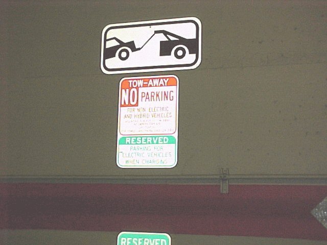
One of the Palo Alto, CA public EV charging spots has extra signage
either addressing hybrids or to make an extra effort to add
clarity that hybrids are not EVs. Since the media calls hybrids
electric cars, they put up different signage at
http://www.evchargernews.com/regions/94301_1.htm
There is another sign partially shown at the bottom of image
http://www.evchargernews.com/photos/94301_1.jpg
California has a State law on the books that allows for the
towing of non-EVs in EV charging spots. Palo Alto's EV charging
locations have signs that clearly state that non-EVs will be
towed away.
http://search.yahoo.com/search;_ylt=A0geuqJsmMtFT2wAjsxXNyoA?p=california+vehicle+code+%22electric+vehicle+charging%22+tow
With this type of EV charging signage:
- non-EVs will be towed-away
- EV charging only
- no hybrids
placed at a SUV's windshield hieght (in their face), the signage
has been very effective to keep their public EV charging spots
from being clogged with fuel vehicles (ICE'd).
I suggest that:
-the three (above) points be stressed at any EV charging spot
-be painted with different colored lines on the asphalt (yellow,
green, or blue)
-and that the EV charging location not be located in a prime
parking location
That last point is quite important. Many Air Quality Management
District [ http://aqmd.gov ] EV charging spot installations were
located in the front of the place of business. EV drivers are not
disabled/handicapped.
When locating a public EV charging spot, first work with the host
to find where electrical power is easily accessible from the
outside. Then of those locations, select parking spots that ICE
drivers would least likely use (the rear or side of a host's
business).
I encourage others to POST EV charging signage they know of. When
the public EV charging spots are up, please let the EV List know
of the image so we can see them. Perhaps, there ought to be a
Euro EV charging map on an Euro EV Association web site.
Bruce {EVangel} Parmenter
' ____
~/__|o\__
'@----- @'---(=
. http://geocities.com/brucedp/
. EV List Editor, RE & AFV newswires
. (originator of the above ASCII art)
===== Undo Petroleum Everywhere
____________________________________________________________________________________
Sucker-punch spam with award-winning protection.
Try the free Yahoo! Mail Beta.
http://advision.webevents.yahoo.com/mailbeta/features_spam.html
--- End Message ---
--- Begin Message ---
I see the subtext of the title is "Good candidate for a hi performance
electric racing car."
48V and 400A? Maybe an RC car; that's 25 HP peak.

Matt Kenigson wrote:
FYI, ran across this on ebay.  Looks pretty old and unsophisticated.
Item # 120084271742
--- End Message ---
--- Begin Message ---
Peter,

The voltage drop is what it means.  It a drop of voltage of the source
voltage measure on that circuit.

If I have a 90 volts at the load end, and its 120 volts at the transformer.
Is this not a 30 volt drop from the reference voltage of 120 volts.

If Its reads 210 volts at the load end, and its 240 volts at the
transformer, this is also a 30 volt drop.

I know its VD = ohms x amps.  But I am talking about the actual voltage at
the end of a circuit.  If this voltage is too low to operated a motor or
other load, than you have to either increase the voltage or increase the
conductor size which decreases the resistance and voltage drop

We have to know what the voltage is to increase it a certain amount of
percentage to bring up the line voltage under load.

If we have a building that has 240 volt transformers feeding it. And the
voltage at the end of circuit reads 230 volts, (a 10 volt drop), we normally
tap up the transformers one 5 percent tap to about 250 volts no load, so we
can have 240 volts on the service.

We do not change any service entrances at this time, even though there is a
10 volt lost by the increase ampere or small conductors.

Roland


----- Original Message -----
From: "Peter VanDerWal" <[EMAIL PROTECTED]>
To: <[email protected]>
Sent: Thursday, February 08, 2007 3:05 PM
Subject: Re: wiring size


> Roland, the point you keep missing is that the total VOLTAGE has no effect
> on the voltage drop in the wires.
> Its ohms's law plain and simple.  The voltage drop in the wire is equal to
> the wire's resistance * the current.  The applied voltage is irelevent.
>
> Yes the size of the conductor affects the voltage drop, but the applied
> voltage does NOT.  You would have the exact same voltage drop on a 240V
> ciruit running 18 amps with the same size conductor.
> Every electician knows this.
>
> The problem is that you were originally saying that voltage drop is a
> percentage of applied voltage, and it's not.  It has NOTHING to do with
> applied voltage. Then you gave an example of battery sag to support your
> position, and this also has NOTHING to do with voltage drop in the wiring.
>
> Voltage drop depends on wire resitance, and in this case, connection
> resistance, and the current.  That's it.
> Wire resistance depends on length and diameter. Connection resistance is
> normally negligible (unless it's a bad connection) but in EVs we tend to
> have a LOT of connections, so it adds up.
>
> To reiterate my point (which has not changed) voltage drop in wiring has
> NOTHING to do with applied voltage, it depends solely on the resistance
> and the current.
>
> > We change out a feeder on a building that had 50 feet of No. Awg 6 wire
> > from
> > the transformer, which was connected to about 100 feet of No. Awg. 10 to
> > a
> > power outlet.  They had a 250 feet of No.12 AWG multi stranded copper
> > wire
> > plug into this power out that ran to a 18 amp load.  They could not
> > understand why the voltage only read 90 volts!
> >
> > There was too much voltage drop for the size of the conductors running
> > 300
> > feet for that load.   We replace the largest ones we can get in the
> > existing
> > conduit, so the voltage drop was now to about 115 volt.
> >
> > Therefore the size of conductor made a difference at the same load of 18
> > amps at the same voltage.
> >
> > If you apply the same voltage and ampere to different size conductors,
> > the
> > smaller conductor will have more voltage drop. Every electrical work
> > knows
> > this.
> >
> > I think the problem we have, is that you said, changing the ampere and
> > distance at the same voltage results in a voltage drop which is true,
> > while
> > I say the ampere and distance is constant, but a reducing the wire size
> > increases the voltage drop which is also true.
> >
> > As electrical workers, we install many different length of conductors on
> > a
> > 20 amp circuit.  So we mainly think of the length of the circuit for
> > that
> > size wire.  The preferred maximum run length of a No. 12 wire is 50
> > feet.
> > At and after 50 feet we use a No. 10 wire on a 20 amp circuit, even
> > though
> > the No. 10 wire is rated for 30 amps.  A No. 8 wire is run for a maximum
> > of
> > 40 feet for a 40 amp circuit and so on.
> >
> > Roland
> >
> >
> >
> >
> >
> > ----- Original Message -----
> > From: "Peter VanDerWal" <[EMAIL PROTECTED]>
> > To: <[email protected]>
> > Sent: Thursday, February 08, 2007 8:59 AM
> > Subject: Re: wiring size
> >
> >
> >> <shakes head>
> >> Roland, at 200 amps a 2/0 cable drops about 0.5V regardless of pack
> >> voltage.  You'll see the same voltage drop at 120V or 240V when
> >> carrying
> >> 200 amps.
> >>
> >> Of course the cable size has NOTHING to do with battery sag which is
> >> what
> >> you are describing.
> >> Battery sag is related to the batteries and has nothing to do with what
> >> size cables you use or how many connections there are, all that matters
> >> is
> >> how much current you pull, the particulars of your battery (some
> >> batteries
> >> sag less than others), and how well charged it is.
> >>
> >> > I said the total run of 50 feet circuit length, which includes the
> >> > 2/0
> >> > cables, cable lugs,  batteries, battery links, contactors, shunts and
> >> > controller. In my EV this is about 3 percent voltage drop in a EV 50
> >> > foot
> >> > circuit which includes the battery links.
> >> >
> >> > I am running 50 feet of circuit length of which the voltage reads 192
> >> > volts
> >> > at no load, and at exactly 200 amp load, my battery voltage reads
> >> about
> >> > 186
> >> > volts which is about 3 percent volt drop of the applied voltage.  I
> >> read
> >> > this ampere and voltage with four industrial meters and also the
> >> > E-meter,
> >> > and they read all the same.
> >> >
> >> > Roland
> >> >
> >> >
> >> >
> >> >
> >> >
> >> >
> >> > ----- Original Message -----
> >> > From: "Peter VanDerWal" <[EMAIL PROTECTED]>
> >> > To: <[email protected]>
> >> > Sent: Wednesday, February 07, 2007 11:26 PM
> >> > Subject: Re: wiring size
> >> >
> >> >
> >> >> I think something is wrong with your math.
> >> >>
> >> >> The voltage drop should be constant at a give current and length,
> >> >> not
> >> a
> >> >> percentage of applied voltage.
> >> >>
> >> >> 1/0 cable has about 0.096 ohms resistance per thousand feet, or
> >> 0.0048
> >> >> ohms for 50 feet.  By my calculations, that works out to ~0.8 volts
> >> at
> >> >> 170
> >> >> amps and ~0.9 V at 195 amps.
> >> >>
> >> >> I don't have a clue how you came up with 10 volts of drop at 195
> >> amps,
> >> >> but
> >> >> that would make a nice space heater (almost 2,000 watts) ;-)
> >> >>
> >> >> > Hello Tim,
> >> >> >
> >> >> > The amperage rating of the conductor depends on many factors.  The
> >> >> type
> >> >> > of
> >> >> > conductor, temperature rating of the insulation, running it in a
> >> >> > close
> >> >> > compartment and the circuit length.
> >> >> >
> >> >> > The circuit length is the total circuit loop length, not just the
> >> >> length
> >> >> > of
> >> >> > run between two points.  In my EV, I have a total run of 25 feet
> >> >> > of
> >> >> > conductor including all the battery lines, to the controller and
> >> >> > to
> >> >> the
> >> >> > motor.  The circuit length is 50 feet.
> >> >> >
> >> >> > 1/0 copper stranded bare wire run in air is good for 175 amps
> >> >> continuous
> >> >> > for
> >> >> > a 3 percent voltage drop.
> >> >> >
> >> >> > A 1/0 copper stranded wire that has a insulation rating of 90
> >> degrees
> >> >> C
> >> >> > or
> >> >> > 194 degrees F is good for 170 amps continuous with a 3 percent
> >> >> > voltage
> >> >> > drop.
> >> >> >
> >> >> > A 2/0 copper stranded wire with a insulation rating of 90 degrees
> >> >> > C
> >> >> > is
> >> >> > good
> >> >> > for 195 amps continuous at 3 percent VD.
> >> >> >
> >> >> > The above distances are at 100 feet circuit length, so the voltage
> >> >> drop
> >> >> > will
> >> >> > be proportional to the length.  At 50 feet circuit length it will
> >> be
> >> >> > about
> >> >> > 1.5 percent voltage drop.
> >> >> >
> >> >> > At 72 volts, it will drop to about 62 volts under a 195 amp load
> >> for
> >> >> > a
> >> >> > 50
> >> >> > foot circuit length.   As you increase the ampere, the voltage
> >> >> > will
> >> >> drop
> >> >> > proportional.
> >> >> >
> >> >> > It would be best to use 2/0 multi strand copper wire with a
> >> >> > voltage
> >> >> > rating
> >> >> > of 300 volts for any voltages under 250 volts and 600 volt rating
> >> for
> >> >> > voltages over 300 volts.
> >> >> >
> >> >> > Roland
> >> >> >
> >> >> >
> >> >> >
> >> >> >
> >> >> > ----- Original Message -----
> >> >> > From: "Tim Gamber" <[EMAIL PROTECTED]>
> >> >> > To: <[email protected]>
> >> >> > Sent: Wednesday, February 07, 2007 8:32 PM
> >> >> > Subject: wiring size
> >> >> >
> >> >> >
> >> >> >> is 1/0 wiring big enough to take 450 amps for short bursts and
> >> >> 100-200
> >> >> >> amps
> >> >> >> continuous at 72 volts?
> >> >> >>
> >> >> >> _________________________________________________________________
> >> >> >> http://local.live.com/default.aspx?v=2&cp=43.658648~-79.383962&style=r&lvl=15&tilt=-90&dir=0&alt=-1000&scene=3702663&cid=7ABE80D1746919B4!1329
> >> >> >> >From January 26 to February 8, 2007
> >> >> >>
> >> >> >>
> >> >> >
> >> >> >
> >> >>
> >> >>
> >> >> --
> >> >> If you send email to me, or the EVDL, that has > 4 lines of
> >> legalistic
> >> >> junk at the end; then you are specifically authorizing me to do
> >> >> whatever
> >> >> I
> >> >> wish with the message.  By posting the message you agree that your
> >> long
> >> >> legalistic signature is void.
> >> >>
> >> >>
> >> >
> >> >
> >>
> >>
> >> --
> >> If you send email to me, or the EVDL, that has > 4 lines of legalistic
> >> junk at the end; then you are specifically authorizing me to do
> >> whatever
> >> I
> >> wish with the message.  By posting the message you agree that your long
> >> legalistic signature is void.
> >>
> >>
> >
> >
>
>
> --
> If you send email to me, or the EVDL, that has > 4 lines of legalistic
> junk at the end; then you are specifically authorizing me to do whatever I
> wish with the message.  By posting the message you agree that your long
> legalistic signature is void.
>
>
--- End Message ---
--- Begin Message ---
Tony,
This is a "How long does it take to travel one mile?" type of question.
The answer is: It depends.
Fuses are essentially a bit of (non ideal) conductive material that will
melt when enough current is passed through it. The factors include, but
are not limited to:
Material
length
cross sectional diameter
ambient temperature
air flow
(and a bunch of other factors Lee will point out)
When the current (and thus voltage) increases sufficiently that the
power (heat generated) is enough to melt the fuse (taking all the above
factors into account), then it blows. Fuses are non-precision devices.
Fusible links tend to have a current rating that is "way too much."
That is, they blow under severe overcurrent conditions. Typically,
they're used as a "weak link" in a wiring system, and are typically
chosen to be four gauges smaller than the wiring they're protecting.
So, your 20 gauge link was designed to protect (melt before) 16 gauge wire.

Tony Hwang wrote:
Hi all,

I have a question about 20 gauge fusible links. Can't find much information
about them,
and not many places to buy them by googling! Anyways, what is the current that
will
trip the fusible link in amps, for say, a 20 gauge fusible link? I'm guessing
15 amps or so?

                        - Tony
--- End Message ---
--- Begin Message ---
Correct,

This is not IGBT technology, not FET, not SCR, but.... transistors!
Real early-age semiconductors design.
It may work, but don't expect that using a 30+ yo design to work
as well as those made with more appropriate components.
I know, there are many guitarists that will take nothing less
than a real tube-amp, but they also know that a tube can't
generate the power for a concert hall PA system.
There is a right tool for every job.

YMMV.

Cor van de Water
Systems Architect
Proxim Wireless Corporation   http://www.proxim.com
Email: [EMAIL PROTECTED]      Private: http://www.cvandewater.com
Skype: cor_van_de_water       IM: [EMAIL PROTECTED]
Tel:   +1 408 542 5225        VoIP: +31 20 3987567 FWD# 25925
Fax:   +1 408 731 3675        eFAX: +31-87-784-1130
Second Life: www.secondlife.com/?u=3b42cb3f4ae249319edb487991c30acb


-----Original Message-----
From: [EMAIL PROTECTED] [mailto:[EMAIL PROTECTED]
Behalf Of Matt Kenigson
Sent: Thursday, February 08, 2007 9:47 AM
To: [email protected]
Subject: Homebrew 400A 48V controller and schematics on ebay


FYI, ran across this on ebay.  Looks pretty old and unsophisticated.
Item # 120084271742
--- End Message ---
--- Begin Message ---
I hope you got at least a wiring diagram with your mystery motor. That
would
certainly help to determine what you have and how to connect it to run it.
----- Original Message -----
From: "Matthew Milliron" <[EMAIL PROTECTED]>
To: <[email protected]>
Sent: Wednesday, February 07, 2007 5:03 PM
Subject: I.d. that motor
 I just came into possession of a new small motor.

Oriental motor Co. RR9
reversible motor 01541
B0160-454
100W       100V    50/60Hz
40uF               10min.


It has 5 wires of 20 gauge.  I assume that it is AC.  Online I find
one site with Oriental motor's.  No help.

R. Matt Milliron
1981 Jet Electrica
http://www.austinev.org/evalbum/702
My daughter named it, "Pikachu". It's yellow and black,
electric and contains Japanese parts, so I went with it.
--- End Message ---
--- Begin Message ---
On a whim I decided to contact them about it to find out.  Here's the response:

Thank you for your interest in Electrovaya's MAYA-100.  How did you
find out about the Maya Zero Emission Electric Vehicle?

The vehicle is not yet commercially available, however, you can
purchase the vehicle directly through us in our early adoption
program. The current early adopter price in North America of the Maya
ZEV is US$70,000 for the entire vehicle, batteries and onboard
charger. This price does not incorporate any operating cost savings,
maintenance cost savings, potential battery leasing arrangements or
potential government rebates.  Please let me know if I can help you
through the purchasing process.

I've attached a specification sheet on the MAYA electric vehicle.
Currently in a compact SUV glider the MAYA-EV has a range of up to 230
mi and highway speeds. The vehicle is based upon one of the world's
most advanced batteries,  Electrovaya's Lithium Ion SuperPolymer(r)
technology. The prototype completed road trials winning the Technology
Award and Battery Electric Vehicle Award at the 2004 Tour de Sol, an
alternative transportation rally.  The field included Toyota's hybrid
Prius, GM's hydrogen powered fuel cell and other vehicles.

If I can get you any more information please don't hesitate to call or
send me an email.

Best regards,

Michael @ Car Inquiry
Electric Vehicle Program
2645 Royal Windsor Drive
Mississauga, Ontario
Canada L5J 1K9
T. 905.855.4610 Ext.3078
F. 905.822.7953
E. [EMAIL PROTECTED]
W. www.electrovaya.com

On 2/3/07, james s <[EMAIL PROTECTED]> wrote:
Sorry this is wrong they did the Smart Car.

On 1/31/07, james s <[EMAIL PROTECTED]> wrote:
>
> Sorry Tony as far as I know the Maya-100 is and was the only one.  I think
> Electrovaya has now built a Mini Copper into an EV and is trying to get into
> the European market.  This is all the info I could get out of someone in the
> Toronto EAA chapter that has dealings with Electrovaya.
>
> James
>
> Toronto, Ontario, Canada
>
>
> On 1/30/07, Tony Hwang <[EMAIL PROTECTED]> wrote:
> >
> > http://www.electrovaya.com/av/ZEV_video.mpg
> >
> > You guys might have seen this already, but it's the first time I've seen
> > it, and it looks really cool! Anyone have any ideas as to the
> > cost/availability of this car?
> >
> >             - Tony
> >
> >
>
--- End Message ---
--- Begin Message ---
Let's apply ohms law in a very simple example:

Assumptions:

Our load is a 10 ohm heater core, which doesn't change with temperature.
Our wire has 1 ohm per 1000 feet.
The leads to the heater are 10 feet long; 5 feet on each leg, 5
milliohms each leg.
We place 150V across this series circuit:

The current through the entire circuit is 14.985A, yielding 2248 watts.
The voltage drop of each wire leg is 75mV (1.12W)
The voltage drop of the heater core is 149.85V (2245W)

Now, increase to 300V:

Current is 29.97A
Voltage drop of each leg is 150mV
Voltage drop of the core is 299.7V
Looks like the voltage drop has doubled, along with the current and the
input voltage.
Let's now assume 150V input, with the same wire, but with a dual coil
parallel core heater where you can switch one coil in and out.
Current is 14.985, with 75mV across each lead leg.
Turn on the second coil, and the core resistance drops to 5 ohms.
Now, wire leg drop is 150mV each, and current is 29.94A

--
Roland is trying to say that the voltage drop of the wires is a
percentage for a _fixed resistive load_. This is correct; see example 1
above. This is true because a fixed load will draw current proportional
to the voltage applied, causing a proportional voltage drop in the
conductors.
Peter is trying to say that the voltage drop is purely a function of
current through the conductor. and the resistance of that conductor.
He's also correct; see example 2 above. This is easily derived from
Ohm's Law.
You seem to be saying that to maintain the same power draw (watts),
you'd need to halve the current if you double the voltage, which is also
correct, but doesn't really seem germane to the conversation at hand,
and certainly isn't what's stated by Ohm's law. Ohm's law does not state
that doubling voltages will halve current. It states that the current
though a conductor is _directly proportional_ to the voltage across it,
and inversely proportional to the resistance of that conductor.
Rick Todd wrote:
Actually Chief, Voltage has every effect on voltage drop.  Ohms law as you
said also states that current will be divided by half when voltage is
doubled.  Hence a voltage drop of 3A at 150V will be 1.5A at 300V. WITH THE
SAME WIRE!
I am getting a little tired of the Egos that are on this list. Roland is
every bit correct.
-Richard Todd
P.E. Electrical Engineering

-----Original Message-----
From: [EMAIL PROTECTED] [mailto:[EMAIL PROTECTED] On
Behalf Of Peter VanDerWal
Sent: Thursday, February 08, 2007 4:05 PM
To: [email protected]
Subject: Re: wiring size

Roland, the point you keep missing is that the total VOLTAGE has no effect
on the voltage drop in the wires.
Its ohms's law plain and simple.  The voltage drop in the wire is equal to
the wire's resistance * the current.  The applied voltage is irelevent.

Yes the size of the conductor affects the voltage drop, but the applied
voltage does NOT.  You would have the exact same voltage drop on a 240V
ciruit running 18 amps with the same size conductor.
Every electician knows this.

The problem is that you were originally saying that voltage drop is a
percentage of applied voltage, and it's not.  It has NOTHING to do with
applied voltage. Then you gave an example of battery sag to support your
position, and this also has NOTHING to do with voltage drop in the wiring.

Voltage drop depends on wire resitance, and in this case, connection
resistance, and the current.  That's it.
Wire resistance depends on length and diameter. Connection resistance is
normally negligible (unless it's a bad connection) but in EVs we tend to
have a LOT of connections, so it adds up.

To reiterate my point (which has not changed) voltage drop in wiring has
NOTHING to do with applied voltage, it depends solely on the resistance
and the current.
We change out a feeder on a building that had 50 feet of No. Awg 6 wire
from
the transformer, which was connected to about 100 feet of No. Awg. 10 to a
power outlet.  They had a 250 feet of No.12 AWG multi stranded copper wire
plug into this power out that ran to a 18 amp load.  They could not
understand why the voltage only read 90 volts!

There was too much voltage drop for the size of the conductors running 300
feet for that load.   We replace the largest ones we can get in the
existing
conduit, so the voltage drop was now to about 115 volt.

Therefore the size of conductor made a difference at the same load of 18
amps at the same voltage.

If you apply the same voltage and ampere to different size conductors, the
smaller conductor will have more voltage drop. Every electrical work knows
this.

I think the problem we have, is that you said, changing the ampere and
distance at the same voltage results in a voltage drop which is true,
while
I say the ampere and distance is constant, but a reducing the wire size
increases the voltage drop which is also true.

As electrical workers, we install many different length of conductors on a
20 amp circuit.  So we mainly think of the length of the circuit for that
size wire.  The preferred maximum run length of a No. 12 wire is 50 feet.
At and after 50 feet we use a No. 10 wire on a 20 amp circuit, even though
the No. 10 wire is rated for 30 amps.  A No. 8 wire is run for a maximum
of
40 feet for a 40 amp circuit and so on.

Roland


----- Original Message -----
From: "Peter VanDerWal" <[EMAIL PROTECTED]>
To: <[email protected]>
Sent: Thursday, February 08, 2007 8:59 AM
Subject: Re: wiring size
<shakes head>
Roland, at 200 amps a 2/0 cable drops about 0.5V regardless of pack
voltage.  You'll see the same voltage drop at 120V or 240V when carrying
200 amps.

Of course the cable size has NOTHING to do with battery sag which is
what
you are describing.
Battery sag is related to the batteries and has nothing to do with what
size cables you use or how many connections there are, all that matters
is
how much current you pull, the particulars of your battery (some
batteries
sag less than others), and how well charged it is.
I said the total run of 50 feet circuit length, which includes the 2/0
cables, cable lugs,  batteries, battery links, contactors, shunts and
controller. In my EV this is about 3 percent voltage drop in a EV 50
foot
circuit which includes the battery links.

I am running 50 feet of circuit length of which the voltage reads 192
volts
at no load, and at exactly 200 amp load, my battery voltage reads
about
186
volts which is about 3 percent volt drop of the applied voltage.  I
read
this ampere and voltage with four industrial meters and also the
E-meter,
and they read all the same.

Roland


----- Original Message -----
From: "Peter VanDerWal" <[EMAIL PROTECTED]>
To: <[email protected]>
Sent: Wednesday, February 07, 2007 11:26 PM
Subject: Re: wiring size
I think something is wrong with your math.

The voltage drop should be constant at a give current and length, not
a
percentage of applied voltage.

1/0 cable has about 0.096 ohms resistance per thousand feet, or
0.0048
ohms for 50 feet. By my calculations, that works out to ~0.8 volts
at
170
amps and ~0.9 V at 195 amps.

I don't have a clue how you came up with 10 volts of drop at 195
amps,
but
that would make a nice space heater (almost 2,000 watts) ;-)
Hello Tim,

The amperage rating of the conductor depends on many factors.  The
type
of
conductor, temperature rating of the insulation, running it in a
close
compartment and the circuit length.

The circuit length is the total circuit loop length, not just the
length
of
run between two points.  In my EV, I have a total run of 25 feet of
conductor including all the battery lines, to the controller and to
the
motor.  The circuit length is 50 feet.

1/0 copper stranded bare wire run in air is good for 175 amps
continuous
for
a 3 percent voltage drop.

A 1/0 copper stranded wire that has a insulation rating of 90
degrees
C
or
194 degrees F is good for 170 amps continuous with a 3 percent
voltage
drop.

A 2/0 copper stranded wire with a insulation rating of 90 degrees C
is
good
for 195 amps continuous at 3 percent VD.

The above distances are at 100 feet circuit length, so the voltage
drop
will
be proportional to the length.  At 50 feet circuit length it will
be
about
1.5 percent voltage drop.

At 72 volts, it will drop to about 62 volts under a 195 amp load
for
a
50
foot circuit length.   As you increase the ampere, the voltage will
drop
proportional.

It would be best to use 2/0 multi strand copper wire with a voltage
rating
of 300 volts for any voltages under 250 volts and 600 volt rating
for
voltages over 300 volts.

Roland


----- Original Message -----
From: "Tim Gamber" <[EMAIL PROTECTED]>
To: <[email protected]>
Sent: Wednesday, February 07, 2007 8:32 PM
Subject: wiring size
is 1/0 wiring big enough to take 450 amps for short bursts and
100-200
amps
continuous at 72 volts?

_________________________________________________________________
http://local.live.com/default.aspx?v=2&cp=43.658648~-79.383962&style=r&lvl=1
5&tilt=-90&dir=0&alt=-1000&scene=3702663&cid=7ABE80D1746919B4!1329
>From January 26 to February 8, 2007
--
If you send email to me, or the EVDL, that has > 4 lines of
legalistic
junk at the end; then you are specifically authorizing me to do
whatever
I
wish with the message.  By posting the message you agree that your
long
legalistic signature is void.
--
If you send email to me, or the EVDL, that has > 4 lines of legalistic
junk at the end; then you are specifically authorizing me to do whatever
I
wish with the message.  By posting the message you agree that your long
legalistic signature is void.
--- End Message ---
--- Begin Message ---
On Fri, 09 Feb 2007 07:43:54 +1100, you wrote:

>G'day Matt
>
>Yup, you've got a little AC motor, 100 watt with only a 10 min run time
>(without mention of the cool-down time or duty cycle). Strange that a motor
>that size should require 40uF, I'd have thought 4uF would be more its' mark.
>
>Hth

  Oriental motor has other newer motors of this kind.  It says they
have an internal brake so they can reverse instantly.  It also has a
special winding for more starting torque.  That may explain the larger
cap.
  However, the motors I could find only had 3 wires.  Mine has two
red, one black, one yellow, one white.

R. Matt Milliron
1981 Jet Electrica
http://www.austinev.org/evalbum/702
My daughter named it, "Pikachu". It's yellow and black,
electric and contains Japanese parts, so I went with it.
--- End Message ---
--- Begin Message ---
Rick Todd wrote:

> Actually Chief, Voltage has every effect on voltage drop.
> Ohms law as you said also states that current will be
> divided by half when voltage is doubled.  Hence a voltage
> drop of 3A at 150V will be 1.5A at 300V. WITH THE
> SAME WIRE!

Hang on; you're confusing the issue even more.

You are assuming that the power drawn by the load is a constant, and so
doubling the supply voltage means that half the current is required to
supply the same load power.

Fact is, you haven't disproved what Peter has correctly stated: the
voltage drop does not depend on the supply voltage, it depends only on
the load current and the resistance of the wire.  You just confused the
issue by coming up with an example that changes two variables (supply
voltage and load current) at the same time.

BTW, Ohm's Law is V/I=R; it doesn't say that current will divide by one
half when voltage is doubled, it says current will *double* when voltage
is doubled unless the resistance is also changed.  Ohm's law applies to
this voltage drop discussion in that the resistance of a given length of
cable will be constant, and so the voltage drop across that run of cable
will be V=I*R.  That is, the voltage drop depends on the current being
carried by the cable and the resistance of the cable, it does not depend
on the source voltage supplying the load current.  Regardless of whether
a 12V or 1200V battery is used, if it supplies a 100A current, the
voltage drop in the cable between it and the load will be the same.
Therefore the initial statement by Roland that describing the voltage
drop as a % of the source voltage is at least misleading; while the drop
he observed may have been an amount that happens to be equal to x% of
the battery voltage he was using, this does not mean that if one used a
battery of half this voltage they would observe 1/2 the voltage drop in
the cable at the same load.

Cheers,

Roger.
--- End Message ---
--- Begin Message ---
Cor van de Water wrote:
This is not IGBT technology, not FET, not SCR, but.... transistors!
Real early-age semiconductors design.
The schematic and parts list don't appear to match the hardware shown.
It may be that someone got the parts list and schematic for a commercial
controller, and built their own. But, they only used 10 power
transistors, while the parts list calls for 24.
Caveat emptor.
It may work, but don't expect that using a 30+ yo design to work
as well as those made with more appropriate components.
--
Ring the bells that still can ring
Forget the perfect offering
There is a crack in everything
That's how the light gets in    --    Leonard Cohen
--
Lee A. Hart, 814 8th Ave N, Sartell MN 56377, leeahart_at_earthlink.net
--- End Message ---
--- Begin Message ---
[EMAIL PROTECTED] wrote:
I have recently converted a 1995 Hyundai Elantra... I have ten 12 volt
Trojans for a total pack of 120 Volts. I have a correctly programmed
Zivan NG3 charger onboard. Today, I was making some measurements while
the car was charging.  I have 3 batteries that are three months newer
than the rest. The voltage on these batteries was around 15.2 volts
when the other batteries were still charging at 13.73 or so. I am
aware of the Zivan charging/equalizing process.
Question: Do I need regulators to even out the charge on each battery? If
so, what brand/make to you recommend? Ang? Rudman? Others?
Being Trojans, I assume these are flooded batteries? If so, the main
consequence of the high charging voltage on the 3 newest batteries is
that they will use more water, and have a shorter life (i.e. they will
get "beaten down" to match the older batteries in the pack).
If you want to reduce their water usage and extend their life,
regulators would help. Or, you could just let them get beaten down so
the whole pack dies at about the same time. With floodeds, it's not so
critical.
The "best" regulators will depend on how much different the batteries
are. You could do some experiments; for example, connect a car tail
light (which draws about 1 amp) across the 3 higher batteries when they
hit 15v. Is that enough so all the batteries end up at the same voltage
when the charger shuts off? See how long it takes them to get back up to
15v again. If it only takes an hour or so, the little zener-lamp
regulators I have described will work. If it takes several hours at 1
amp, then you'll need something more aggressive.
--
Ring the bells that still can ring
Forget the perfect offering
There is a crack in everything
That's how the light gets in    --    Leonard Cohen
--
Lee A. Hart, 814 8th Ave N, Sartell MN 56377, leeahart_at_earthlink.net
--- End Message ---
--- Begin Message ---
Hi David,

If these are floodeds, then in theory they can take a decent
over-charge, so as long as the charge current is not too large
and the 3 hitting 15V is towards the end of the charging, they
should be OK without regs, just slightly more over-charged
than the rest.

If the imbalance is too big to just let it go and you expect that
the difference between the new and old batteries is not too big
then you can apply "zener regs" to nudge them closer together.
Alternatives are mostly self-built, the theory is not difficult
but finding something that keeps working over time, temp and
abuse is another thing.
I am actually implementing a reg solution that not only does
essentially the same as the zener regs (bypass 1/2 Amp) but also
gives me a signal at undervoltage (10.5v) to lift the foot from
the accelerator and a signal when the first reg turns on
(to throttle the charger back) and when the last one hits
(charging finished).
This allows me to control the charger to avoid over-charging
my AGM batteries, while guaranteeing a decent charge on all of them.
I'll post it when it works to my satisfaction.

Cor van de Water
Systems Architect
Proxim Wireless Corporation   http://www.proxim.com
Email: [EMAIL PROTECTED]      Private: http://www.cvandewater.com
Skype: cor_van_de_water       IM: [EMAIL PROTECTED]
Tel:   +1 408 542 5225        VoIP: +31 20 3987567 FWD# 25925
Fax:   +1 408 731 3675        eFAX: +31-87-784-1130
Second Life: www.secondlife.com/?u=3b42cb3f4ae249319edb487991c30acb


-----Original Message-----
From: [EMAIL PROTECTED] [mailto:[EMAIL PROTECTED]
Behalf Of [EMAIL PROTECTED]
Sent: Thursday, February 08, 2007 1:12 PM
To: [email protected]
Subject: Regs? Opinions Please?


Hello group,

I've been a lurker for a long time and have learned a lot from you all.  I
have recently converted a 1995 Hyundai Elantra and have loved driving it.  I

have ten, 12 volt Trojans for a total pack of 120 Volts.  I have a correctly

programmed Zivan NG3 charger onboard.  Today, I was making some measurements
while
the car was charging.  I have 3 batteries that are three months newer than
the rest. The voltage on these batteries was around 15.2 volts when the
other
batteries were still charging at 13.73 or so.  I am aware of the Zivan
charging/equalizing process.

Question:  Do I need regulators to even out the charge on each battery?  If
so, what brand/make to you recommend?  Ang?  Rudman?  Others?

THANK YOU VERY MUCH!

<http://www.austinev.org/evalbum/887>

David in Georgia
--- End Message ---
--- Begin Message ---
On Feb 8, 2007, at 2:05 PM, Peter VanDerWal wrote:
The problem is that you were originally saying that voltage drop is a
percentage of applied voltage, and it's not.  It has NOTHING to do with
applied voltage. Then you gave an example of battery sag to support
your
position, and this also has NOTHING to do with voltage drop in the
wiring.
I thought he was suggesting that the *acceptable* voltage drop is
usually considered as a percentage of the applied voltage. If 3% is
taken as an acceptable number (I'm not sure exactly what is acceptable)
then a 96 volt EV running at 200 amps can use smaller wire than a 48
volt EV at 200 amps. 3% is almost 3 volts in the first case but not
quite 1.5 volts in the second.
Paul "neon" G.
--- End Message ---
--- Begin Message ---
The video clip of the KillaCycle running 8.760 at Las Vegas is now
over 20,000 views on YouTube and appears to be accelerating. Over 600
views in just the last day!
http://www.youtube.com/watch?v=3dRpAZci9m0
Bill Dube'
--- End Message ---
--- Begin Message ---
         From another list,

The Fuel Cell 2007 Conferene is June 14-15 at the Hyatt
Regancy in
Rochester, NY. For more infomation on attending please visit
www.fuelcell- magazine. com

                          Jerry Dycus
--- End Message ---
--- Begin Message ---
I found this company on the web and they sell over 65,000 fuses and
the prices seem good. The owner has been in the business over 20
years and knows all about fuses. Their site is being redone but the
phone number is 805-532-1566. I got a couple 20A 250V Freraz fuses
for a couple bucks each- great service as well. Discount Fuse, they
have an ebay store with a sample of items at:
http://stores.ebay.com/Discount-Fuse


Mark
--- End Message ---
--- Begin Message ---
Hey Bob -

We got electric railways all over the place her in the midwest.
Unfortunately, they call them bike paths now.

Except for the South Shore (a true electric interurban), the IC Electric (a
suburban service) and the old Chicago El they are all gone. But the South Shore
RR - what a jewel she is!

I don't think of my EV as a ICE car with an electric motor.
It's a streetcar with rubber tires.

You know, they used to have coal burning stoves in those trolley cars to keep
warm.
Hmmm. That would feel good right about now in my EV.
Would make it more perky, too.

Dana


 -------------- Original message ----------------------
From: "Bob Rice" <[EMAIL PROTECTED]>
>
> ----- Original Message -----
> From: "Death to All Spammers" <[EMAIL PROTECTED]>
> To: <[email protected]>
> Sent: Thursday, February 08, 2007 12:52 AM
> Subject: Hub Motors, was Re: Porsche invented the hub -mounted electric
> motor
>
>
> > Speaking of which, I just watched FutureCar on Discover channel where
> > the creator of the Eliica points out one of the 8 100hp hub motors -
> > wild looking car!
> >
> > > I will try later this week.
> > >
> > > Cor van de Water wrote:
> > > > The list does not allow attachments.
> >
> > > > Subject: Porsche invented the hub -mounted electric motor for his
> > > > Porsche - Lohner Chaise exhibited in 1900 at the paris world's fair
> > > >
> > > >
> > > > He set several speed records with his hybrid and raced it
> > regualry. He
> > > > also sold a variant of the hybrid to the firedepartments of the day.
> > > >Hi EVerybody;
> >  Also, Transit outfits like New Jersey's Public Service had gas/ electric
> buses,back in the twenties and thirties, that could operate as trackless
> trollies where there was overhead, or light up their gas engine to go
> wireless. Being ice electric, as Diseasel Locomotives are still today, they
> elininated the gear shifting stuff and were smooth runners.
>
>     Somebody mentioned to help clean up CA's air, electrify the RR's Good
> start. In only a few months you could lay perfected third rails, Long Island
> RR has been third railin' for 100 years, along the key RR routes out of LA
> an' SF. Run 'em out, of town, about 50 miles, equip the diseasels with 3rd
> rail shoes. make them get out of town on clean electric power, lighting up
> the Diseasel out in the desert somewhere.This has been going on for 50 years
> on the New Haven RR in NY and CT. I actually SAW a FL-9 origional,last week,
> on the Danbury shuttle, training back from BBB. Still grinding out the
> miles, as one of the OLDEST Diesel Lokies in service, on the planet. They
> were delivered in the mid fifties, held down the Blue ribbon NH jobs;
> "Yankee Clipper"," Merchant's Limited." Saved time by blowing through New Ha
> ven without the traditional Diesel to Electric and vice versa, time honored
> tradition since 1914. They talked in 1915 of electrifying to Boston , it was
> finished 6 years ago. We don't rush into things on the RR!Generous Electric
> is making P-42's with the 3rd rail option. Drag out yur checkbook, how many
> would you like?
>
>     Of course you would hafta upgrade a freight diseasel to run on third
> rail; You have to pile in a DC controller. Hmmm? Otmar? He does the amps
> needed for a Diseasel Zilla<g>!Just get the zillas volts up to 600? 2400
> amps at that power will spin a lokie's wheels all ya want!But you DON't
> want! You want the TORQUE!Or pull 20k tons of stuff for Wal*Mart, out of the
> container terminal. I think Union Pathetic has some Rail Power(google Rail
> Power) switchers, in LA. Basicly they are crammed with nice heavy Lead Acid
> batteries. Here weight is your friend! A 100 hp Disesel genny to keep them
> fresh, a plug in hybrid if you like?
>
>    A good start, Training wheels for the RR biz<g>! Sorry, just sorta
> slipped out.There is nothing as good as an electric for trains. Loved my
> AEM-7's HHP-8's and Acelas, and 50 year old GG-1's You could MOVE stuff
> FAST!Passengers and freight.Sorta like electric cars, once you have driven,
> you don't wanna go back to ICE power!Was nice of Amtrak to lend me their
> electric best for years, and they EVen PAID me!Drive the electric to the
> electric, best way to go.Home to Penn Station, or South Station. Of course
> the voltages varied<g>!
>
>      Flowing with the Current
>
>      Bob
> >
> >
> > --
> > No virus found in this incoming message.
> > Checked by AVG Free Edition.
> > Version: 7.1.411 / Virus Database: 268.17.29/673 - Release Date: 2/6/07
> >
> >
>
--- End Message ---