Hi Maurice,

>
>
> 1) could you please send me also the board with only these 3 modules (usb,
> qfn, pogo_pin)? (no net, just edge and 3 modules would be fine)
> it would be easier check the probs
>
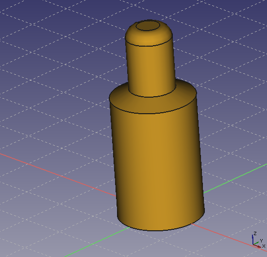
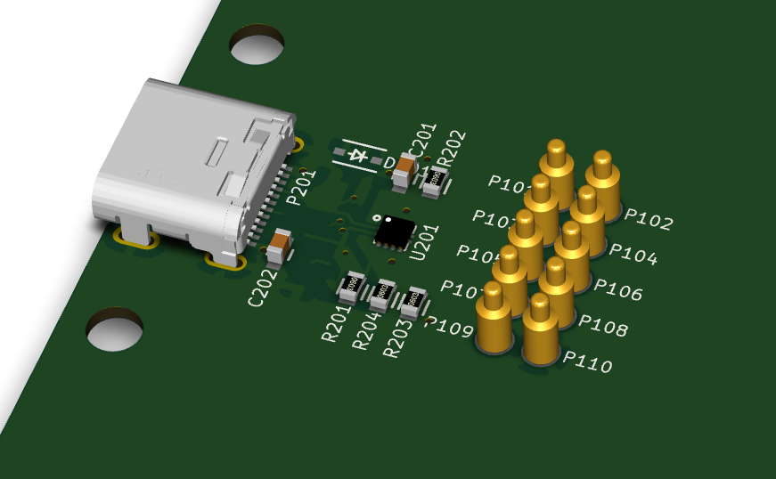
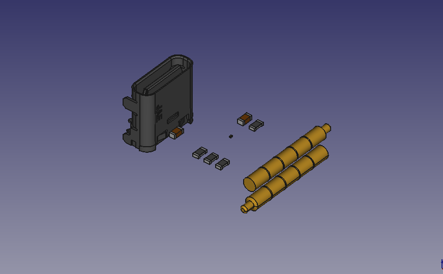
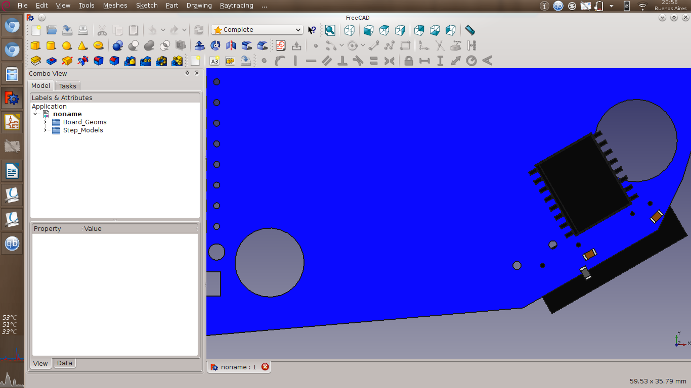
You'll find the design files here
https://github.com/paltatech/std-mainboard

In my computer the 3D files are in
/usr/local/share/kicad/modules/packages3d/walter/step/


2) fusion with color is possible in FC 015 and 016 ... I'm going to send
> the X2QFN-12 fused with color asap ... wich command do you use?
> Part, Make a union of several parts?
>

I'm using part->make compound (in part workbench)
or part->boolean->union (also in part workbench)


> 4) could you please send me also a copy of the trouble pcb edge (no net no
> modules), to check if the problem is in kicad exporting to IDF or in
> importing IDF from FC
>

Also included in the github repo. The outline was imported from a DXF file
generated with freecad. The 3Dviewer displays it correctly, but I think the
error is in the DXF importer because "Global spread and place" -> "spread
out footprints not already on board" didn't detect the outline, so it
probably has a disconnected segment somewhere and 3DViewer is flexible
enough to display it despite the errors

Thanks


>
> thank you
> Maurice
>
> On 19/08/2015 17.13, Marcos Chaparro wrote:
>
>> About the USB connector, don't follow the original part from the
>> manufacturer, it took me a while to align it.
>>
>> Here is the step and vrml of that connector. Its the same manufacturer
>> step, but aligned.
>> http://www.paltatech.com/files/USB-C.zip
>> and the connector footprint:
>> http://www.paltatech.com/files/USB-C-DX07S.kicad_mod
>>
>> The IDF export is not the problem, trying with a simpler outline
>> generates the pcb okay but the parts are still rotated.
>>
>> Regards
>>
>>
>> Marcos
>>
>> On Wed, Aug 19, 2015 at 11:44 AM, Marcos Chaparro <[email protected]
>> <mailto:[email protected]>> wrote:
>>
>>     Hi Maurice,
>>     I just compiled the latest kicad version and the script says
>>     IDF board has to be exported to Xref=0; Yref=0
>>     pcbnew version >=6091
>>     IDF board has NOT to be exported to real placement
>>     pcbnew version < 6091
>>
>>     Anyway, the board is perfectly aligned now, thanks!
>>
>>     I'm using kicad Version: (2015-08-18 BZR 6103)-product release build
>>     and freecad 0.16
>>
>>     I do have a question, the tutorial says "assure that your STEP
>>     module is fused to just one solid object". I see it failing with
>>     multi part obejcts, but I don't know how to fuse a part properly in
>>     freecad.
>>
>>     A boolean operation between parts (union) creates a "fusion" object
>>     that loses color information.
>>     Going through "make compound" in the part workbench seems to be the
>>     right way to do it, but the script is still not happy with the
>>     generated step file and in freecad you can see its not a single
>> object.
>>
>>     See attached an example of a part that I can't fuse together
>>     (X2QFN). I think there are no coplanar faces in the part.
>>
>>
>>     Also, pogo_pin.step looks fine to me in freecad, but when it is
>>     added to a board using the script it gets rotated. Its also attached
>>     http://www.paltatech.com/files/pogo_pin_in_freecad.png
>>     http://www.paltatech.com/files/USB-C_3dviewer.png
>>     http://www.paltatech.com/files/USB-C_stepup.png
>>
>>     The usb connector that is also rotated is here
>>
>> http://www.jae.com/z-en/product_en.cfm?l_code=EN&series_code=DX07&product_number=DX07S024JJ2R1300
>>
>>     I'm also having throubles exporting the pcb to IDFv3 of this
>>     particular board, maybe this is related to these rotation issues. I
>>     should ask cirilo later about this.
>>
>>     Thanks
>>
>>
>>
>>
>>
>>     Marcos
>>
>>     On Tue, Aug 18, 2015 at 7:17 PM, easyw <[email protected]
>>     <mailto:[email protected]>> wrote:
>>
>>         Hi Marcos,
>>
>>         it took me a bit but I managed to align the board.
>>         Now the script can manage also circular board, board with arcs
>>         and pcb rotated inside pcbnew.
>>
>>         I also made an update for the board position for the new IDF
>>         exporting grid.
>>
>> http://sourceforge.net/projects/kicadstepup/files/kicad_StepUp_v0.519.zip/download
>>         NB this version will put the board at the right position only if
>>         IDF is exported to Xref=0;Yref=0 (pcbnew version > 6091)
>>
>>         I added a starter guide (adoc and pdf) both for kicad StepUp
>>
>> http://sourceforge.net/projects/kicadstepup/files/kicadStepUp-starter-Guide.pdf/download
>>         and for FreeCAD script generator.
>>
>> http://sourceforge.net/projects/kicadstepup/files/FC-script-generator-starter-Guide.pdf/download
>>
>>         I patched also the scripting to generate 3D models in STEP, to
>>         be execute correctly also in linux (cadquery freecad module has
>>         been updated too).
>>         (I tested the scripts in ubuntu but it should work also in debian)
>>
>>         Please have a look :)
>>
>>         Maurice
>>
>>
>>
>>         On 14/08/2015 16.02, Marcos Chaparro wrote:
>>
>>             Thanks Maurice,
>>             the board edge is actually a footprint, and it was rotated
>>             180° in
>>             kicad_pcb file, I don't know if that matters.
>>
>>             About 2), you're right, freecad 0.14 messed up the vrml
>>             export. I tried
>>             with 0.16 and it looks perfect. I'm on a debian box, the
>>             stable freecad
>>             version for us is 0.14, in order to get 0.15 I had to
>>             compile it, and since
>>             it was the same effort as getting the bleeding edge I
>>             compiled 0.16.
>>
>>             I keep forgetting that gmail's inline images are not shown
>>             here, the
>>             screenshot in my last mail was this one (thanks Mario)
>>             www.paltatech.com/files/offset.png
>>             <http://www.paltatech.com/files/offset.png>
>>
>>             Thanks
>>
>>
>>
>>             Marcos
>>
>>             On Fri, Aug 14, 2015 at 5:46 AM, easyw <[email protected]
>>             <mailto:[email protected]>> wrote:
>>
>>                 Hi Marcos, thank you for the board...
>>
>>                 1. I had a quick look and I see the position prob...
>>                 IDF import in FreeCAD, with this complex edge board,
>>                 adds a rotation and
>>                 probably the center of rotation is not fine ... I' m
>>                 going to investigate a
>>                 bit more if this depend on import or export or on my
>>                 calculations...
>>
>>                 2. about the rendering of wrl model SIL7, which version
>>                 of FC did you use
>>                 to export it?
>>                 I tried your wrl in kicad and is not well displayed,
>>                 then I exported the
>>                 STEP model to wrl in FC 0.15 and the rendering is fine...
>>                 I will post the wrl model when I'll be back home.
>>
>>                 Thank you again for your feedback
>>
>>                 Maurice
>>
>>                 On 14 August 2015 01:59:39 CEST, Marcos Chaparro
>>                 <[email protected] <mailto:[email protected]>>
>>                 wrote:
>>
>>                     This should work, see attached a test board
>>
>>                     [image: Inline image 1]
>>
>>                     The SIL7 model is awful, somehow it looks ok in
>>                     freecad and really bad
>>                     in
>>                     kicad.
>>
>>
>>
>>                     Marcos
>>
>>
>>                 --
>>                 Sent from Mobile
>>
>>
>>
>>
>>
_______________________________________________
Mailing list: https://launchpad.net/~kicad-developers
Post to     : [email protected]
Unsubscribe : https://launchpad.net/~kicad-developers
More help   : https://help.launchpad.net/ListHelp