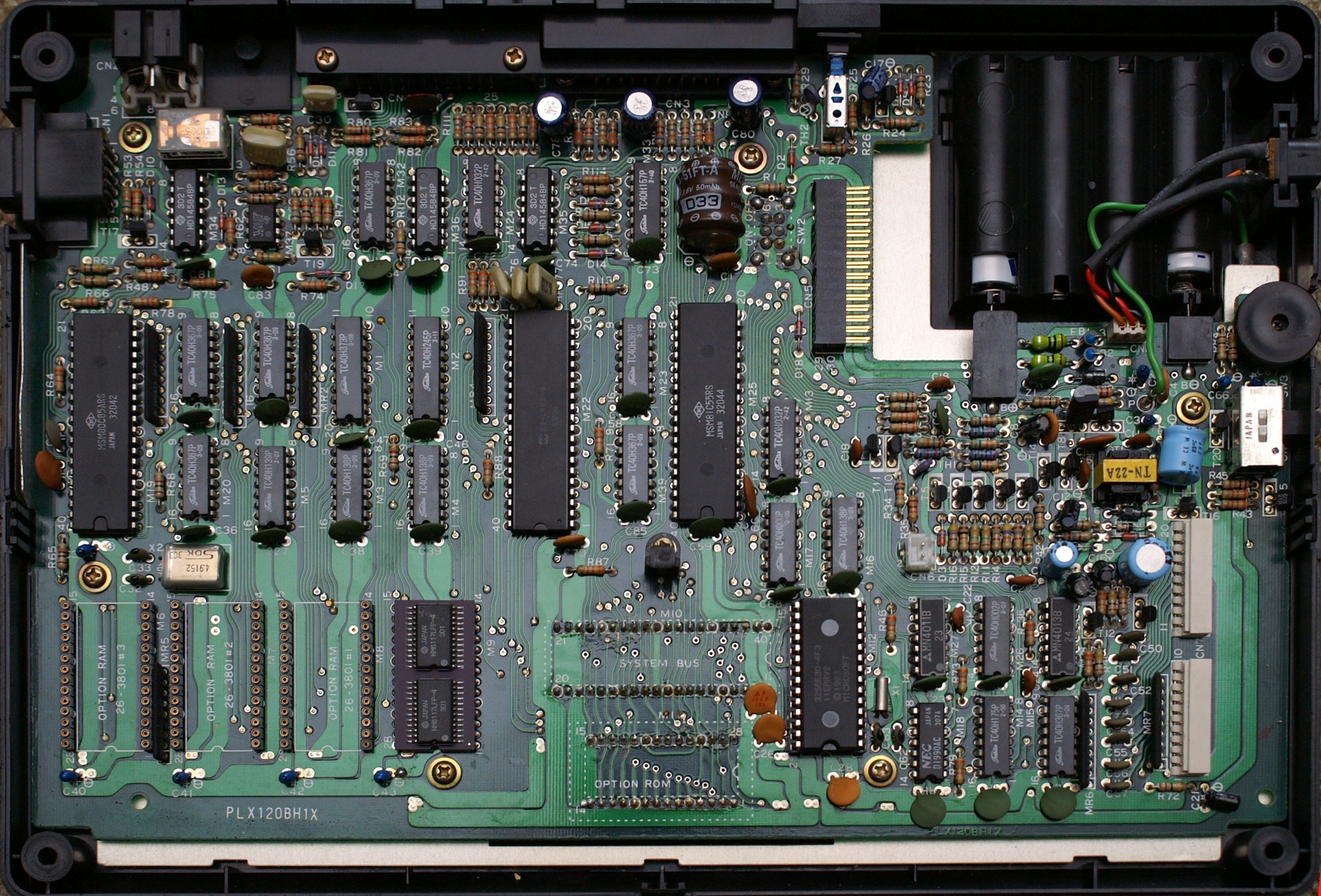
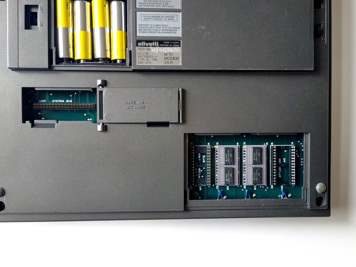
Examples about the ram sockets:

A 100 motherboard, round sockets:
http://www.mvcsys.de/doc/remem_pics/full/mainboard.jpg
By contrast Olivetti usually (but not always) has leaf style:
https://ascii.jp/img/2022/03/03/3331148/o/e1be81b188aad285.png

--
bkw

On 3/24/24 15:46, Eric wrote:
It's been a while since I sent out an update, but I wanted to let
everyone know that the M100 is working! Turns out there were multiple
issues.
Problem 1: A11 was stuck in a high state. Thanks to the advice from
PeterN, I used nippers to zero into the faulty IC (M21 Pin 14).
Problem 2 and 2.5: Found two bad ram modules (M8 and M9). This
surprised me, I was only expecting one to be bad. Thanks to Jeff Birt
for his open source SDRAM tester
(https://www.youtube.com/watch?v=5fFRrfUjogs
<https://www.youtube.com/watch?v=5fFRrfUjogs>). I built it and it
helped me identify the faulty ram.
So, the M100 is currently running with 2 of 4 ram modules. I think it
would be fun to build a couple modules to replace the faulty ones. It
looks like there are a few designs on the forum so I think that will be
the next project. Let me know if anyone recommends a specific design to
build.
Thanks again for everyone's assistance!

Eric
On Thursday, January 4, 2024 at 07:27:48 PM PST, Peter Noeth
<[email protected]> wrote:
Back in the 70's and 80's, when I used to do component level repair on
Mini Computers (15" square PCBs in a card cage with an average of 150
TTL and CMOS ICs running at 5 volts), it was common practice to use a
sharp, close cutting, pair of nippers to cut the lead of an DIP IC at
the point where it enters the PCB to isolate it from the rest of the
circuit to debug problems like this.
Mind you, this was on PCBs with 8 to 12 circuit layers, so protecting
the PCB from trace damage was the top priority. We never removed an IC
unless we were absolutely sure it was defective. If isolating a suspect
IC lead this way proved not to be the cause, it was pressed back into
place and a solder bridge connected it back to the pad.
My experience is that it was extremely unlikely for the input pin of an
IC to be the guilty culprit when a signal was stuck high (above 3
volts), but it sometimes happened when a signal was stuck low (below 2
volts). The most common cause was an output pin of an IC.
I still use this method when I have to isolate PCB circuit problems.
Always isolating and checking output pins first.
Regards,

PeterN
On Thu, Jan 4, 2024 at 1:03 PM <[email protected]
<mailto:[email protected]>> wrote:
    Send M100 mailing list submissions to
    [email protected] <mailto:[email protected]>

    To subscribe or unsubscribe via the World Wide Web, visit
    http://lists.bitchin100.com/listinfo.cgi/m100-bitchin100.com
    <http://lists.bitchin100.com/listinfo.cgi/m100-bitchin100.com>
    or, via email, send a message with subject or body 'help' to
    [email protected]
    <mailto:[email protected]>

    You can reach the person managing the list at
    [email protected] <mailto:[email protected]>

    When replying, please edit your Subject line so it is more specific
    than "Re: Contents of M100 digest..."


    Today's Topics:

        1. Re: Model 100 - LCD Shows Pixels Only ([email protected]
    <mailto:[email protected]>)


    ----------------------------------------------------------------------

    Message: 1
    Date: Wed, 3 Jan 2024 15:04:44 -0600
    From: <[email protected] <mailto:[email protected]>>
    To: <[email protected] <mailto:[email protected]>>
    Subject: Re: [M100] Model 100 - LCD Shows Pixels Only
    Message-ID: <[email protected]
    <http://soigeneris.com>>
    Content-Type: text/plain; charset="utf-8"

    Is it possible that your CTRL or BREAK key are not working, thus you
    are not able to do a cold reset? It could also be the M2 data bus
    latch has the bit you mentioned stuck. Sometimes you can look at a
    suspect bit on the oscilloscope and see incorrect voltage levels, or
    what looks like multiple signals at once. Note that with the
    multiplexed bus this can be difficult to spot as there are some
    ?normal? goofy looking waveforms when the bus is being multiplexed.

    The code for the test harness test ROM is here:
    https://github.com/Jeff-Birt/TRS-80-M100-M102-Test-Harness
    <https://github.com/Jeff-Birt/TRS-80-M100-M102-Test-Harness> . The
    test harness ROM board has a small built in LCD for feedback. You
    won?t have this but you can follow how far it gets though the test
    with your LA.


    Jeff Birt


    From: M100 <[email protected]
    <mailto:[email protected]>> On Behalf Of Eric
    Sent: Wednesday, January 3, 2024 10:23 AM
    To: [email protected] <mailto:[email protected]>
    Subject: Re: [M100] Model 100 - LCD Shows Pixels Only


    Yes, I did hold down CTRL+BREAK+press reset.  Repeated this three
    times and the data is almost identical (repeatable results).  I
    triggered off of the reset signal and recorded 100ms pre-trigger and
    2s post-trigger.  Performed data review just after the RESET occurred.


    Thanks again for everyone's help with this.  I'm learning a lot
    about this computer and feedback from the forum has been very
    inspiring!


    On Wednesday, January 3, 2024 at 05:12:15 AM PST, <
    <mailto:[email protected] <mailto:[email protected]>>
    [email protected] <mailto:[email protected]>> wrote:


    -------------- next part --------------
    An HTML attachment was scrubbed...
    URL:

<http://lists.bitchin100.com/private.cgi/m100-bitchin100.com/attachments/20240103/1cd45bc8/attachment-0001.htm

<http://lists.bitchin100.com/private.cgi/m100-bitchin100.com/attachments/20240103/1cd45bc8/attachment-0001.htm>>

    ------------------------------

    Subject: Digest Footer

    _______________________________________________
    M100 mailing list
    [email protected] <mailto:[email protected]>
    http://lists.bitchin100.com/listinfo.cgi/m100-bitchin100.com
    <http://lists.bitchin100.com/listinfo.cgi/m100-bitchin100.com>


    ------------------------------

    End of M100 Digest, Vol 157, Issue 3
    ************************************
--
bkw