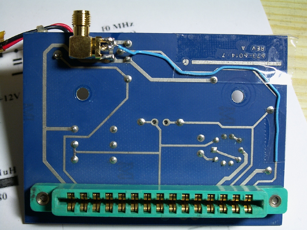
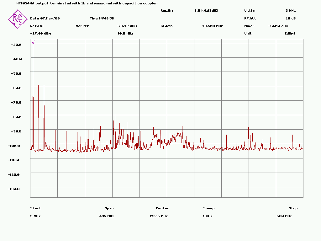
Esa Heikkinen wrote:
> I also doubt that there could be something wrong with emitter follower
> so I also did some tests with "capacitive coupler" build on bottom PCB
> of the HP10544:
> http://www.amigazone.fi/files/gpsdo/544coupler.jpg
> (1 kohm. terminaton is not visible on the picture)
>
> Generally it's just a wire going over 10 MHz trace on the PCB and then
> it's connected to the spectrum. By this way it's possible to measure the
> output without loading it with any galvanic connection. Of course there
> is almost 30 dB of loss but it's not any trouble with spectrum analyzer
> having over -145 dBm noise floor.
>
> But with that kind of measure the output specrum looks like this:
> http://www.amigazone.fi/files/gpsdo/544-5.png
>
> So there's less harmonics but 2nd and 3rd are still high if compared
> with other OCXO's. Hard to say anything of higher harmonics because that
> kind of coupler takes in all background noise like FM broadcasts etc. so
> I wouldn't trust these measurements too much (and because of that I
> didn't even mention them at first).
>
>
Esa
The distortion now appears to be within specification.
You cant expect much better given the 10544A internal buffer amplifier
topology.
Your can always use relatively high Q traps for the 2nd and 3rd
harmonics if they are a problem.
The best location for these is within your external low distortion
buffer amplifier.

It would seem likely that the scope measurements with a ~ 50pF load are
misleading, try for a 10pF or lower load capacitance.
Your external emitter follower also has significant distortion when
driving a 50 ohm load.

Bruce

_______________________________________________
time-nuts mailing list -- [email protected]
To unsubscribe, go to https://www.febo.com/cgi-bin/mailman/listinfo/time-nuts
and follow the instructions there.