Hi Bruce

> A more efficient buffer like a white emitter follower using 2 x npn + 1
> x pnp would be best.
> If you want I can post such a circuit using BC546 + BC556 or similar.
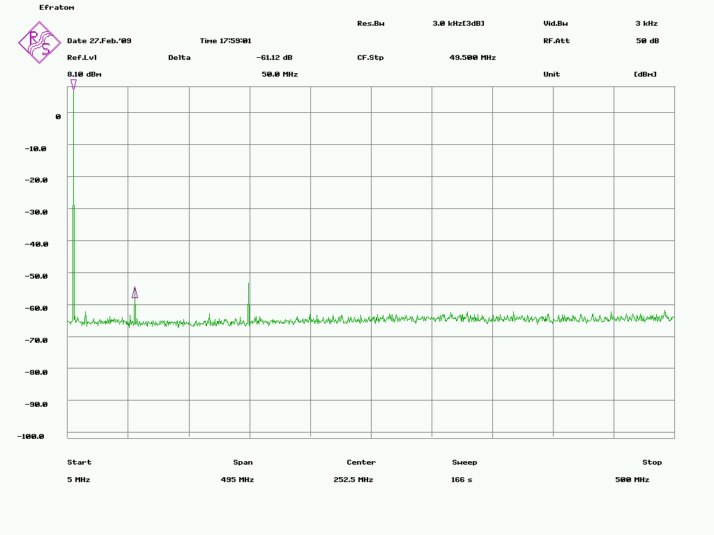
Yes if you have that kind of schematic I'd like to test it. It won't
take much time to do breadboard testing. I have BC547's and BC557's
ready in the shelf, all E12 resistor values are available but capasitors
and coils are not so easy; of course any standard values like 100n, 10n,
22...33p etc. are available at a moment. Coils are most difficult
however LCR meter is available but I don't have any cores that might be
necessary to make coils for this purpose?

> This buffer needs to be located with 5cm or less of the OCXO connector
> unless you use capacitance cancellation techniques.

Ok.. there was a "bottom PCB" used all my previous tests, which itself
has about 5 cm. trace before coaxial connector. I don't know where this
PCB is originally used. It included 12V regulator and some filtering.
But maybe i could get the signal directly from output pins without using
a coax at all, with just a pair of very short wires and take the OCXO as
close as breadboard as possible.

> First you need to decide what output level you want:
> +7dBm? +13dBm?

Many instuments seems to want as much as 1V input for external
reference. That seems odd because the level is so high that it will
cause a 10 MHz spurious peak easily. So I think the +13 dBm should be
enough. There will be some kind of distribution amplifier in final
design and I have no idea about it's gain (not selected any yet). But
let's assume it will have gain of 1:1.

> The how far do you need to suppress the 2nd and 3rd harmonics?

There's no specification for these. But if we think about the
application which is to clean the LPRO's output signal it would be nice
to have at least same kind of harmonics performance that LRPO itself
has. It has some kind of lower grade crystal inside but I have no idea
maybe there are some filtering because the spectrum is fine:
http://www.amigazone.fi/files/gpsdo/LPRO-3.PNG

Some spurious on 50 MHz and below 150 MHz still present.

> You need to set some actual specs.

I think good spec is that it has to clean the LPRO's output, not get it
worse. I know it's main purpose is rubidium noise cleaning, which is not
seen in these spectrum measurements at all and I even don't have the
cleaning loop yet.

I'm trying to pass on step by step so first thing is to find out how to
generate a good 10 MHz signal and next thing will be that (digital?)
phaselock needed to lock that on rubidium at suitable timing constant.
Then there will be another stage to control LPRO's C-field with GPS,
some diagnostics, power supplies, distribution amplifier etc... Lot's of
work to do. Infact I had no idea how hard it is to get just a clean 10
Mhz...

> Attenuating them by 20dB is easy if you need to suppress them much
> further it gets more difficult.

Yes that's the point I'm afraid with 10544.

> Don't use a high Q bandpass filter as its phase shift tempco will be
> relatively high.

What do you think if I could find FM radio IF filter somewhere (10.7
MHz) and tune it to 10 MHz? I don't know if there's tunable filters
available anymore because any new ones seems to be ceramic. But maybe
from some old radio could have tunable one (wishful thinking in Finland,
thanks to "recycling" of the electronics).

--
73s!
Esa
OH4KJU

_______________________________________________
time-nuts mailing list -- [email protected]
To unsubscribe, go to https://www.febo.com/cgi-bin/mailman/listinfo/time-nuts
and follow the instructions there.