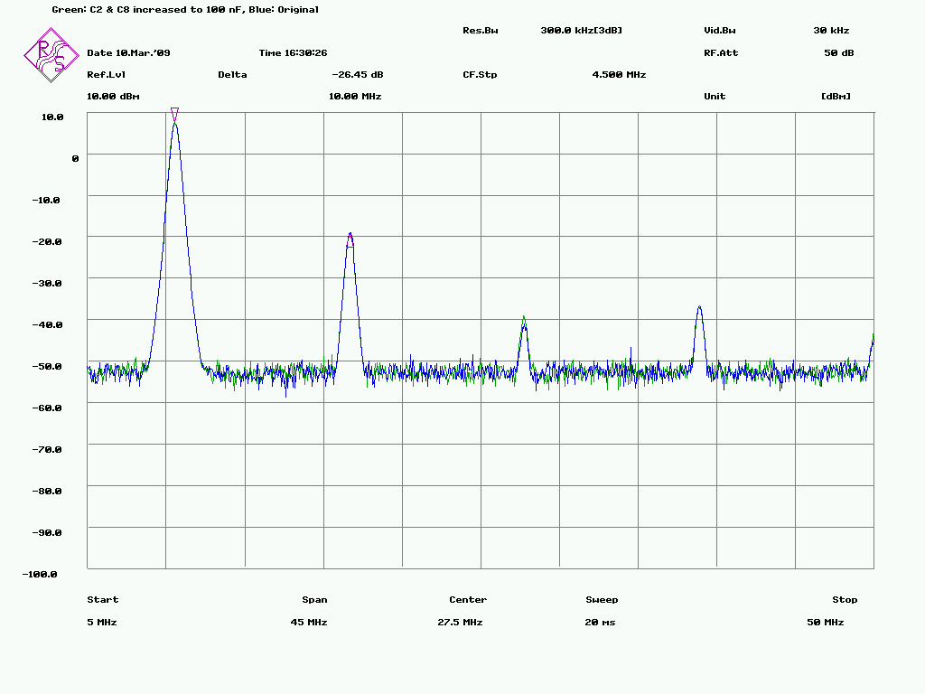
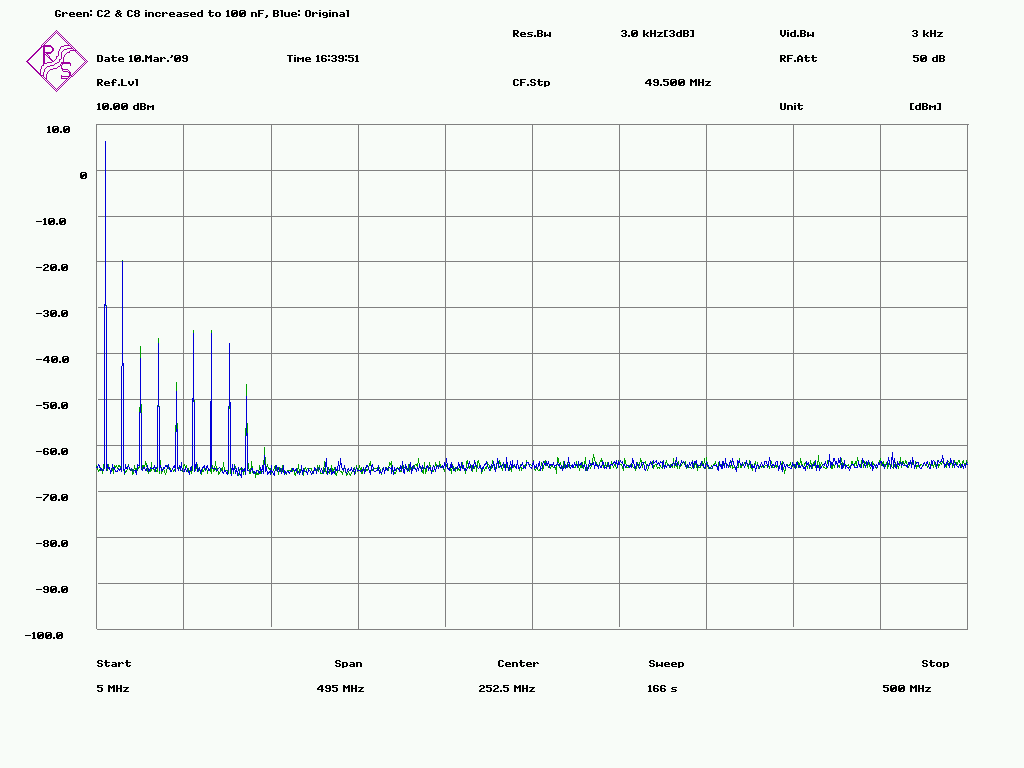
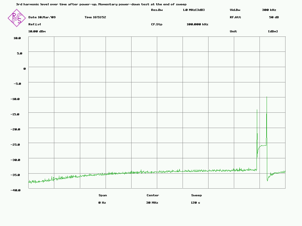
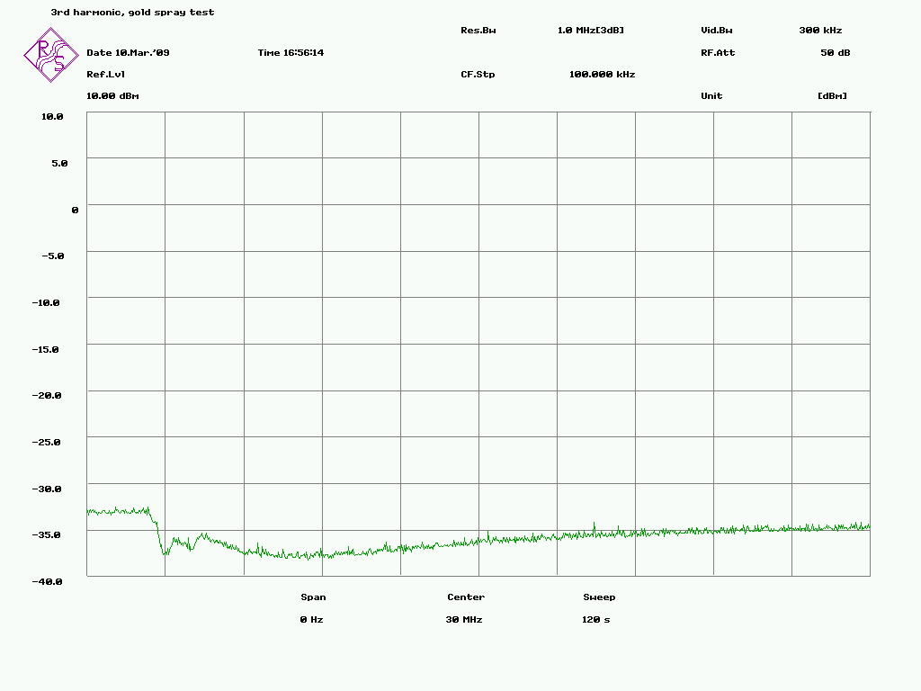
Esa Heikkinen wrote:
> Hi Bruce...
>
>
>> Try increasing C2 and C8 in the white emitter follower circuit schematic
>> to 100nF.
>>
>
> Doesn't seems to change anything:
> http://www.amigazone.fi/files/gpsdo/544-15.png
> http://www.amigazone.fi/files/gpsdo/544-16.png
>
> When doing this measurement I noticed that the 3rd and higher harmonics
> level are changing! First I thought that the capacitor change was some
> effect on harmonics but then those peaks come back...
>
> Time domain analysis about 3rd harmonic level gave some explanation:
> http://www.amigazone.fi/files/gpsdo/544-17.png
>
> The EF circuit was turned on at start of sweep. Something is heating and
> raising the harmonic level. The bump and the end of sweep is a test
> where I momentary switch off the 12V feed to the EF circuit to see how
> it reacts.
>
> Temperature sensitivity was also verified with cold spray:
> http://www.amigazone.fi/files/gpsdo/544-18.png
>
> Well, that's not an issue but makes measurements harder because even
> without any changes the results can differ. However the temperature
> effect on the 2nd harmonic frequency was very small.
>
>  > The switcher sidebands will still be there, they are just buried in
>  > the spectrum analyser noise floor.
>
> Yes you're right. Just changed some settings and there they are again:
> http://www.amigazone.fi/files/gpsdo/544-19.png
>
> About 90 dB below carrier.. I would say that it's good enough! The LPRO
> for example, gives higher spuriouses, but far away from fundamental.
>
>  > Does the board use the recommended LC filters and regulator for the
>  > oscillator supply as depicted in Figure 3 on the 10544A data sheet?
>
> I haven't analyzed it fully but it seems to be just the datasheet
> circuit having LM723, 10 uH coil etc. But it's layout is totally wrong
> because oven switcher current runs via wrong trace. It would also been
> possible to have other side as grouding copper but this was not done.
> The PCB is manufactured by Cubic western data.
>
>  > The required parts shouldn't be too expensive, however you may need
>  > to wind your own inductors for the series tuned LC circuits.
>  > Air core or powdered iron core inductors should be OK as long as you
>  > use shields between filter sections etc.
>
> Sounds like hard. How it's possible that lower grade ocxo's (like in
> thunderbolt) output so much better spectrum? Is it all about ocxo output
> driver circuit? Would it be easier to modify the 10544A itself than
> trying to clean the distortion? Has anyone tried that kind of modification?
>
>
Esa
The attached circuit schematic is for a slightly modified white emitter
follower that reduces the temperature dependence of the input transistor
collector current.
It also increases the loop gain slightly.

Bruce
<<inline: White-emitter-followerV2.gif>>
_______________________________________________
time-nuts mailing list -- [email protected]
To unsubscribe, go to https://www.febo.com/cgi-bin/mailman/listinfo/time-nuts
and follow the instructions there.