>Hal Murray hmurray at megapathdsl.net
>"Would you please say more?  Or post pictures?
>
>Where did you find a 200 ms PPS pulse?"
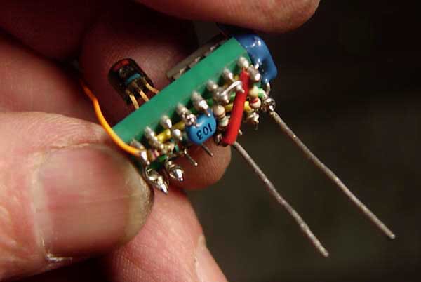
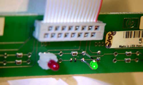
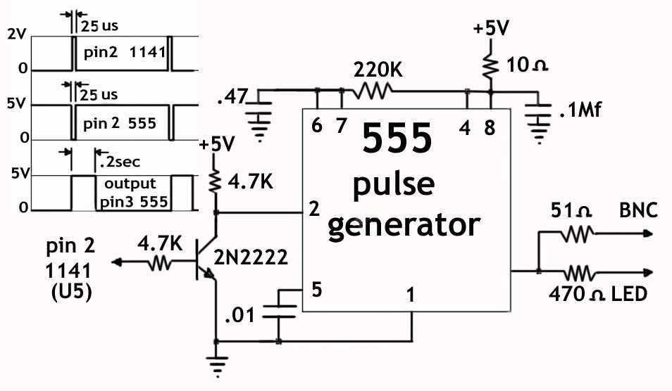
The circuitry I added takes the narrow positive going timing pulse
(2V/25us) on pin 2 of the surface mounted Lucent 1141 IC (U5)
near the DB25 output connector on the main pc board and uses
a single NPN transistor to inverts it to produce a negative going
5V pulse to trigger a 555 pulse generator. The generator output
is a 5volt positive pulse about 0.2 seconds wide that can drive an
LED as well as give a 1PPS rectangular waveform output to an
added BNC connector on the rear panel. The reason I used .2sec
for the pulse is so it would be long enough to be seen on the LED
I mounted on the front panel.

The modification only requires one 555 IC that is used to generate
the .2 second wide 1PPS pulse, 1 general purpose NPN transistor
(2N2222), 6 resistors, 1 LED, and 3 capacitors. All parts used are
common and I mounted them on a 16-pin dip socket with 2 stiff
resistor leads soldered to pads on the main board labeled ‘J3’
where the right rear corner pad I believe was the +5V and the 3rd
pad from the right was ground, but you’ll have to check that to make
sure.

The circuit board on the front panel already has properly spaced
and positioned holes for an LED but there is no hole in the panel
so you’ll have to drill one. I have a photo of how I mounted it but
you’re on your own making that modification.

http://farm8.staticflickr.com/7054/7035510675_fa49693f36_z.jpg
http://farm8.staticflickr.com/7251/6889434938_951a57e093.jpg
http://farm8.staticflickr.com/7253/7035489479_c0bdb34dbf_b.jpg
_______________________________________________
time-nuts mailing list -- [email protected]
To unsubscribe, go to https://www.febo.com/cgi-bin/mailman/listinfo/time-nuts
and follow the instructions there.