The schematic of the converter I attached to my previous message did
not make it through in my copy of the message, so it may be missing
from other people's copies, as well. If anyone wants it and did not
receive it, it is available at:
<http://www.febo.com/pipermail/time-nuts/attachments/20140710/9fb493f1/attachment-0001.jpg>
Best regards,

Charles
Bruce wrote:
Currently Linear Technology's sine to square wave devices with selectable
filtering (LTC6957 series) are better in that they are a closer
approximation to
the ideal zero crossing detector.
Failing that the next best is perhaps an AC coupled (both at input
and between
emitters) differential pair of 2N3906's or similar.
My initial results with the LTC6957 did not produce lower phase
noise at 10MHz than an optimized Wenzel two-PNP circuit (it may be
possible to do better than my initial experiments with the 6957).
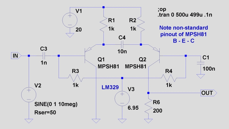
Here is the circuit I use:

Emacs!
Using a 20v supply reduces the input feedthrough due to Q1's B-E
capacitance, which tends to give the output square wave a sloping top.
Using MPSH81s rather than 2N3906s helps with feedthrough, also, as
well as reducing the rise and fall times (both about 2-4 nS with
this circuit, depending on how hard it is driven, if it is built
with proper attention to layout and stray capacitance).
Some will insist that the LM329 is overkill, but the base bias can
be a significant source (even the dominant source) of phase
noise/jitter. The stability and low noise of the 329 improve
performance materially -- even a TL431 or 1N829 is measurably
inferior. An LM399 is somewhat better than the 329, but I have not
found it necessary in practice. (Note that the pullup resistor is
not shown -- 1.5k to 10k metal film from the 329 to +20v, not critical.)
Some additional improvement can be achieved by using the PNP devices
in an HFA3096 or HFA3128 array, but I have generally not seen the
need for this in practic. As drawn, this circuit has lower residual
PN than any 10MHz oscillator I have measured.
Works best with input levels from 1 to 10Vpp (350mV to 3.5Vrms sine
wave). There is a small duty cycle asymmetry (high longer than
low), which depends on drive level. Using faster devices (such as
HFA3096 or HFA3128) reduces the asymmetry. If this is a problem, a
resistor can be added from the base of Q1 to ground to trim out the
asymmetry if the input level is well controlled. Otherwise, the
mean output voltage can be detected, compared to a reference, and
used to adjust either base voltage with a servo loop.
Best regards,

Charles
_______________________________________________
time-nuts mailing list -- [email protected]
To unsubscribe, go to https://www.febo.com/cgi-bin/mailman/listinfo/time-nuts
and follow the instructions there.