Another potential issue is that the setup should be adjusted for minimum AM
sensitivity.Because of diode mismatch and phase mismatch between the internal
transformers this doesn't occur when the mixer dc output is zero. To find the
correct point a dc offset needs to be introduced at the input of the PLL
integrator. The offset is adjusted to minimise AM sensitivity. In order to do
this an AM modulator with very little incidental PM is required.This is tricky
to implement although it has been done using an unbalanced Mach-Zehnder
interferometer plus a pure Phase modulator (easy to do since AM detectors
aren't phase sensitive):
Microwave Sources of Pure Phase and Amplitude-‐Modulated Signals E. N. Ivanov
This adjustment is important as the residual AM of most RF sources isn't
negligible.The technique works uses standard components and techniques (3 db
hybrids, mixers, voltage controlled phase shifters, lock in amplifiers) and
works at far lower frequencies than microwave.
At lower frequencies simpler AM modulators may suffice but you would need to
show that any incidental PM they produce is insignificant in that it wont have
a significant effect on the depth of the AM null at the mixer/phase detector
output.Typically a modulation frequency in the audio band would be used.
Bruce
From: Oleg Skydan <[email protected]>
To: Discussion of precise time and frequency measurement <[email protected]>
Sent: Thursday, 31 March 2016 9:28 PM
Subject: Re: [time-nuts] Oleg' s PN test Re: A new member & PN test set
--------------------------------------------------
From: "Bruce Griffiths" <[email protected]>
> You actually need to measure the filter
> response.
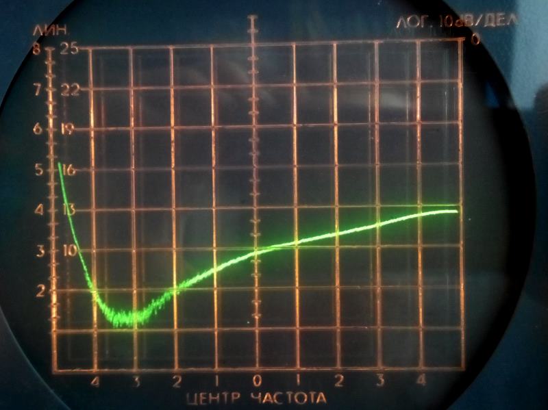
OK. It is here (the frequency span is 2..102MHz, the amplitude axis is
10dB/div):
http://skydan.in.ua/PNTestSet/PN_LPF1.jpg
Sorry, the network analyzer is a bit older than I am :), but it is still in
a good condition. At 100MHz we still have more than 40dB attenuation. The
inductor I used is low Q axial choke, so I do not expect multiple resonances
at higher frequencies - there should be large losses and inductor will look
much more like a resistor (at least until we go too high). The capacitors in
the pi-LPF are 0805 SMD good quality ones.
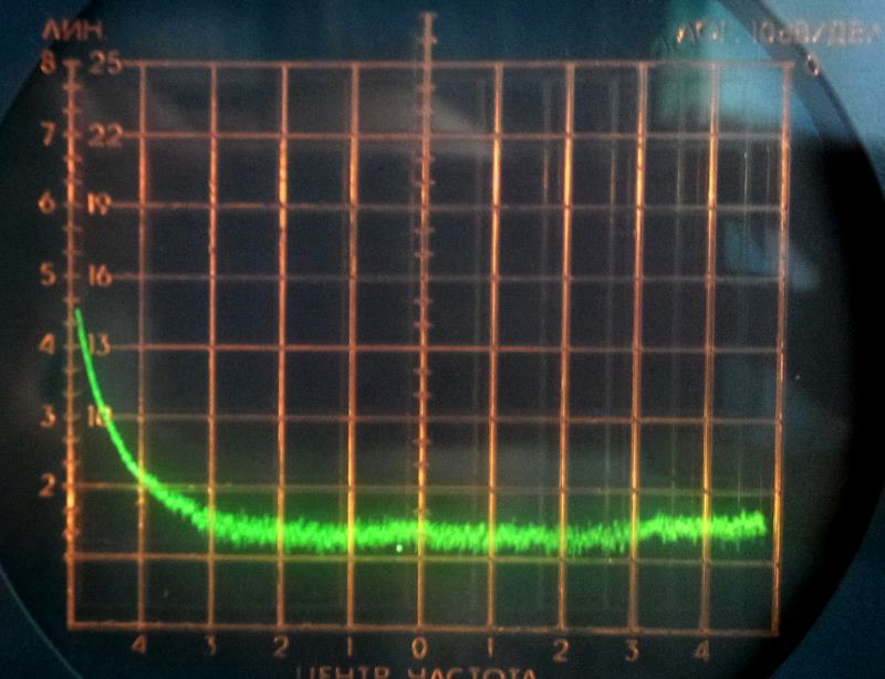
But, we all like perfect things :), so I tried to make the LPF a bit better
adding the BLM31AJ601SN ferrite bead in series with the inductor. Here is
the result:
http://skydan.in.ua/PNTestSet/PN_LPF2.jpg
I like it :)
I also did another test checking DC shift at the AD797 output when the mixer
was fed with two signal generators (there should be no DC - only different
combinations of RF/LO signals). I recalculated all signal levels to LNA
input point.
Before installing the bead the DC shift was:
<150MHz less than 150uV
150..250MHz less than 400uV
250..500MHz less than 1mV
After installing the bead:
<260MHz less than 80uV
There is one big peak near the 300MHz where the DC goes up to 900uV, and
several smaller peaks (up to 250uV) higer, up to 500MHz.
When the two mixer ports are fed with the same signal (inphase) the DC
voltage at LNA input is 130..150mV. With no RF at the mixer ports DC
unbalance is 20uV (all voltages recalculated to LNA input).
The filter can be made even better by cascading several pi sections using
different capacitors and inductors/beads. But as far as I understand, with
the current filter even at 500MHz it will not move too far from the
quadrature, and at 60MHz everything is definitely OK.
All the best!
Oleg
_______________________________________________
time-nuts mailing list -- [email protected]
To unsubscribe, go to https://www.febo.com/cgi-bin/mailman/listinfo/time-nuts
and follow the instructions there.
_______________________________________________
time-nuts mailing list -- [email protected]
To unsubscribe, go to https://www.febo.com/cgi-bin/mailman/listinfo/time-nuts
and follow the instructions there.