Hi Jay,

Building a mains frequency monitor is a great way to expose yourself to almost
everything about precise time & frequency and measurement -- for a few dollars.
Working with quartz, rubidium, cesium simply moves the decimal place over a few
digits.
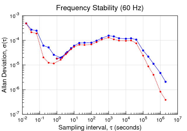
Have a look at:

http://leapsecond.com/pages/mains/

http://leapsecond.com/pages/mains-cv/

It turns out that worrying about how to measure the exact zero-crossing of
every 50/60 Hz cycle to the microsecond has little to no effect on any mid- to
long-term analysis that you do. The low-level microsecond phase noise quickly
averages away. You can see that here:

http://leapsecond.com/pages/mains/mains-adev-mdev-gnuplot-g4.png

The main thing you want to avoid is accidentally missing a cycle, or
accidentally adding a cycle. But a glaring 16 ms gap is so easy to spot.

Some people go through elaborate electronics and filtering to avoid this.
That's fine. Whatever works for you.

I use a picPET through a 5 VAC transformer with no filtering and just measure
what shows up. Once in a great while, due to excessive noise, I see a stray
pulse. But the cool thing about timestamping counters is that if a pulse shows
up when you know it isn't expected you can just delete that data point in s/w
and all is well. Similarly, if for whatever reason you miss a cycle, you just
interpolate it in s/w. I get glitches like this at the rate of a few a year.
There are about 2 billion 60 Hz cycles a year so this level of data repair is
fine with me. Over the past 5 years the worst problem is city-wide power
failures. But in those cases I just trade data with Hal Murray, who is in the
same grid as me, but a different state.

So I think between the two of us we have a complete record of 60 Hz phase going
back years. Check the time-nuts archives as this interesting subject of mains
monitoring comes up a every year or two.

I logged data every cycle for a while. Then I switched to every second. Even
that's more than enough.

Some people use transformers, or opto-isolators, or RC filters, or Schmitt
triggers, or even 60 Hz PLL's. Just pick one that you think will work and play
with it for a couple of days or weeks and see how you like it. I also run a
wall-mount, synchronous motor, kitchen clock to keep me honest. You can see
that, compared to a cesium clock, here:

http://leapsecond.com/pages/tec/mains-clock-ani.gif

/tvb

----- Original Message -----
From: "Jay Grizzard" <[email protected]>
To: <[email protected]>
Sent: Wednesday, April 06, 2016 6:21 PM
Subject: [time-nuts] Building a mains frequency monitor


> Since it seems to be a week for new projects on time-nuts... ;)
>
> So I've been wanting to set up a power line frequency monitor for a while,
> and now(ish) seemed to be a good time for me.
>
> So initially, I was planning on doing a simple design that was posted here
> a couple of years back, which basically works out to:
>
>  mains -> simple 9v ac/ac power brick -> dropping resistor -> picPET
>
> I have a good 10MHz reference to feed the picPET, so this seems like it
> would make a good first shot. But, of course, I eventually want to do
> better than just a first shot. So, I have questions!
>
> Q1: Assuming the schmitt trigger in the picPET triggers at a consistent
> point in the waveform, the frequency at any given cycle is easy to
> calculate: 1.0 / (timestamp2 - timestamp1)    ...but, is there a better
> way? That method just feels... naive, for some reason.
>
> Q2: What are the sources of noise in this design? Assuming the picPET is as
> accurate as my 10MHz reference is, I can think of a few potential places
> that phase noise could creep into the measurements:
>  - Whatever is in the power brick beyond the transformer (I don't think a
> step down transformer alone would add phase noise, right?)
>  - The dropping resistor will slowly change the amplitude of the waveform
> (and thus the point in the cycle that the schmitt trigger fires) due to
> thermal and aging effects, if we're measuring anything that's not the exact
> zero crossing
>  - The point at which the schmitt trigger in the picPET fires will change
> over time for the same reasons. Also potentially due to picPET input voltage,
> depending on how the comparitor is built
>  - Am I missing any?
>
> Q3: The open-ended question: How do I improve on this? I suspect the main
> place for improvement will be in the trigger, but I'm not sure where to go
> with that.  Most designs I've seen involve a schmitt trigger, generally with
> reference voltages set by things like voltage dividers. This seems dubious at
> best, to me, since that means the reference voltage will be affected by the
> same effects I'm calling out above. Is there a *specific* design (rather than
> "make a zero crossing detector!" or something similarly vague) that someone
> can point me to, that would minimize this kind of trigger noise?
>
> Q3.1: Is there a better way to get mains voltage down to something I can work
> more directly with? I saw at least one design that just used a couple of
> megaohm resistors inline -- does that introduce appreciably less phase noise
> than random AC/AC power brick?
>
> I apologize if any of this is overly basic. I've actually read everything I
> could find both in the time-nuts archives and the internet at large about
> this kind of project, but I've still found myself left with the questions
> above.
>
> I appreciate any comments / feedback / pointers!
>
> -j
> _______________________________________________
> time-nuts mailing list -- [email protected]
> To unsubscribe, go to https://www.febo.com/cgi-bin/mailman/listinfo/time-nuts
> and follow the instructions there.
_______________________________________________
time-nuts mailing list -- [email protected]
To unsubscribe, go to https://www.febo.com/cgi-bin/mailman/listinfo/time-nuts
and follow the instructions there.