I am looking for an established and widely accepted procedure for verifying
performance of high resolution time counters.
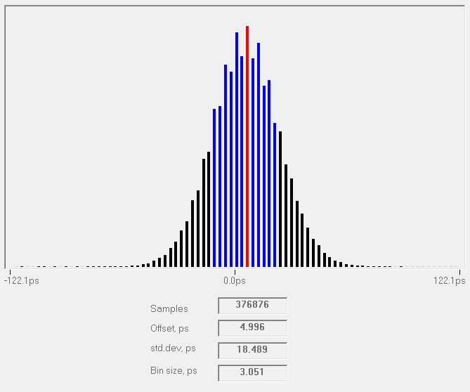
I have designed a time stamping counter for qualifying 1PPS signal performance
against external reference (e.g. 10MHz master clock.)

Simple design verification check I am doing at the moment is gating random
selection of master clock edges back into device's signal input and letting the
device measure this test signal offset against its reference clock - which, for
ideal design, should result in zero offset (modulo 100ns.)  My results are
roughly in line with what I expect to see
http://leobodnar.com/balloons/NTP/time-sampler-test1.png

Now, what would be recognised procedure for sweeping external input pulse delay
over few hundred ns in a controlled, measurable and repeatable way?

I can see few naïve approaches:
1) Using selectively gated (or divided) reference clock followed by adjustable
delay line.  E.g. something like mechanically adjusted delay lines used in HP
test sets.  Or, perhaps, calibrated rigid coax sections?
2) Slightly offset another master clock (e.g. second Rb oscillator) gated in a
similar way but without delay line, followed by statistical data analysis
3) Trusted pulse generator with high resolution delay adjustment fed from the
same master clock as the counter

I am looking for something with ~10ps accuracy, 100ns+ range, and reasonably
low jitter (~5ps or better.)
It is possible that the range needs to be split up (e.g. fixed rigid coax delay
line followed by a mechanically adjust section.)

This is a low budget fun project so something simple and common sense is
preferred to "price on application" NIST traceable equipment.

Thanks!
Leo
_______________________________________________
time-nuts mailing list -- time-nuts@febo.com
To unsubscribe, go to https://www.febo.com/cgi-bin/mailman/listinfo/time-nuts
and follow the instructions there.