Hi Jan-Derk

this is maybe a bit offtopic, but if you don't mind I would like to ask anyway:
is this a DMTD system you have built yourself? I saw a lot of messages on this
topic in the archive, but didn't find where it started.
Since I would also like to do some clock stability measurements but don't have
a HP 53131A or SR620, I thought the DMTD would be a good technique because it
allows to measure picosecond phase errors without actually having a TIC with
that resolution.
I only have a HP 5335A and 5316A, both of which don't have very high resolution
and are thus perhaps not suitable to measure stability of OCXOs, but with a
DMTD, it could be possible.
What oscillator do you use as the offset oscillator, and what is the reference
you use?
I wonder whether it would be possible to use a HP 8662A or 8663A low phase
noise signal generator as the offset oscillator. Because these can be adjusted
in frequency for a beat signal which is convenient to measure. And the phase
noise or stability of the offset oscillator is not of very high importance in
DMTD measurements.
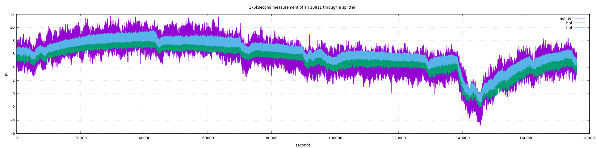
Best
Tobias
HB9FSX

________________________________________
From: time-nuts [[email protected]] on behalf of Jan-Derk Bakker
[[email protected]]
Sent: Monday, November 04, 2019 10:33
To: Discussion of precise time and frequency measurement
Subject: Re: [time-nuts] A simple sampling DMTD

Dear Bob,

I understand the general concern: perfect synchronization would potentially
turn the Dual Mixer Time Difference system into a Single Mixer Time
Difference setup. (Even with perfect synchronization, the dual-channel
architecture would serve to attenuate the common mode component of the ADC
aperture jitter and the rest of the front end).

In the Sherman & Roberts NIST paper I mentioned earlier the authors use a
3kHz PLL loop bandwidth without apparent ill effect. From my measurements
of the drift behavior of my VCTCXO I'm considering much lower bandwidths
(10..50mHz, possibly even lower when I substitute a VCOCXO for the offset
oscillator). While I feel this should be safe doing so, I admit I need to
look harder at the underlying math (and pointers are always welcome).

Sincerely,

JDB.


On Mon, Nov 4, 2019 at 3:00 AM Bob kb8tq <[email protected]> wrote:

> Hi
>
> Yes, it only will be fully correlated well inside the loop bandwidth. The
> loop bandwidth
> normally used for this sort of thing is >> 1 Hz. By the time you start
> doing ADEV, you
> are in the correlated region.
>
> Bob
>
> > On Nov 3, 2019, at 3:42 PM, Jan-Derk Bakker <[email protected]> wrote:
> >
> > Hi Bob,
> >
> >> If you phase lock the downconversion reference, the VCXO noise that now
> > is uncorrelated
> >> between the channels will become correlated. That may make things worse
> > rather
> >> than better
> >
> > Does the impact not depend on the loop bandwidth and VCXO performance?
> If I
> > read it correctly, in "Oscillator metrology with software defined radio"
> (
> > https://aip.scitation.org/doi/10.1063/1.4950898 /
> > https://arxiv.org/abs/1605.03505 , section B, first paragraph) the
> authors
> > implement a sampling DMTD on a USRP B210 SDR platform, with the local
> VCXO
> > PLL'ed to the input from their maser; I'm looking at a similar setup
> (with
> > the expected LO performance being significantly worse than the incoming
> > signals).
> >
> > JDB.
> >
> > On Sun, Nov 3, 2019 at 2:40 PM Bob kb8tq <[email protected]> wrote:
> >
> >> Hi
> >>
> >>> On Nov 2, 2019, at 8:41 PM, Jan-Derk Bakker <[email protected]>
> wrote:
> >>>
> >>> Dear all,
> >>>
> >>> Attila got me thinking with his remark:
> >>>
> >>> I am a bit astonished by the high noise level you have. I would have
> >>>> expected
> >>>> this to yield something below 1ps, judging from what we got from what
> >>>> Nicolas
> >>>> acheived in his work on the sine exitation based TIC[1].
> >>>
> >>>
> >>> ...and I realised that I'm expressing the error wrong. What I had
> >>> calculated was the standard deviation of the entire signal (noise +
> >>> drift/wander). For short time periods I do get sub-ps noise levels,
> even
> >>> without correcting for LF/DC errors.
> >>>
> >>> It may make more sense to look at the Allan deviation. I've used tvb's
> >>> adev1 tool ( http://www.leapsecond.com/tools/adev1.htm ), with a
> manual
> >>> correction to accommodate the 10sps data. To investigate the effect of
> >> high
> >>> pass filtering and attenuating even-order harmonics, I've generated
> >>> 1001-point high pass and band pass FIR filters with GMeteor (
> >>> http://gmeteor.sourceforge.net/ ; the odd size of 1001 points being
> the
> >>> largest size I could reliably get the program to generate filter
> >> solutions
> >>> for); the BPF was generated to have nulls at 20, 40, 60 and 80Hz. 10MHz
> >> was
> >>> generated with an 10811 that had been powered up for three days after
> >>> having been in storage for over a year, its output fed to a
> Mini-Circuits
> >>> ZFSC-2-1 splitter, connected to the DMTD with two 3in semi-rigid
> cables.
> >>> The test was run for 175k seconds (just over 2 days) in a very much
> >>> non-temperature controlled attic. The resulting ADEV can be found at
> >>> http://www.lartmaker.nl/time-nuts/DMTD%20self-noise%20ADEV.pdf ; the
> >>> measured time difference between the channels is
> >>> http://www.lartmaker.nl/time-nuts/DMTD%20self-noise.png ; the input
> >>> spectrum of channel 1 with and without the filters is
> >>>
> >>
> http://www.lartmaker.nl/time-nuts/DMTD%20self-noise%20input%20spectrum.pdf
> >>>
> >>> For tau=1s the Allan deviation without any filtering is 9.5E-13. High
> >> pass
> >>> filtering to eliminate LF noise and drift improves this to 4.6E-13;
> >> adding
> >>> bandpass filtering yields 3.2E-13. Out to 1000s the adev decreases
> >> linearly
> >>> with tau, after that performance degrades (further testing in a
> >> temperature
> >>> controlled room should show whether this is intrinsic or not).
> >>>
> >>> As the high pass filtering seems to have the largest impact, I plan to
> >>> implement this first (still based on averaging over a single period
> >>> centered around the rising flank of the sine; the on-board processor
> >>> doesn't have enough horsepower to run a 1001pt FIR at 2ksps). Next I
> want
> >>> to add code to phase lock the on-board VCTCXO to the reference input,
> >>
> >> If you phase lock the downconversion reference, the VCXO noise that now
> is
> >> uncorrelated
> >> between the channels will become correlated. That may make things worse
> >> rather
> >> than better
> >>
> >> Bob
> >>
> >>> this
> >>> should also make it easy to implement a notch filter to eliminate
> (even)
> >>> harmonics. After that I want to see if I can get a computationally
> >>> efficient arcsin/arctan applied to the data, to make it easier to
> extend
> >>> the number of samples used by the ZCD without running into linearity
> >>> issues. Meanwhile I'm working on a daughterboard with twin Lattice
> iCE40
> >>> FPGAs.
> >>>
> >>> Any suggestions so far?
> >>>
> >>> To be continued,
> >>>
> >>> JDB.
> >>>
> >>>
> >>> On Tue, Oct 22, 2019 at 12:33 AM Jan-Derk Bakker <[email protected]>
> >> wrote:
> >>>
> >>>> Dear Attila,
> >>>>
> >>>> Thank you for your feedback, replies inline:
> >>>>
> >>>> On Tue, Oct 15, 2019 at 6:01 PM Attila Kinali <[email protected]>
> wrote:
> >>>> [snip]
> >>>>
> >>>>> The biggest change I would make, would be to use a higher sampling
> >>>>> frequency and use an FPGA with a CORDIC as phase detector. Especially
> >>>>> as your goal is to measure the phase difference of a distribution
> >> system,
> >>>>> where the frequency of both inputs is exactly the same.
> >>>>>
> >>>>
> >>>> That's the next step (after I've taken this 8-bit processor as far as
> it
> >>>> can go). I'm working on a daughterboard with dual Lattice iCE40
> >> UltraPlus
> >>>> FPGAs, picked mainly because an open toolchain is available, but also
> >> for
> >>>> their price and QFN48 package options (which I've not found in any
> other
> >>>> FPGA family of similar density).
> >>>>
> >>>> (note that for my purposes I do need to DMTD different frequencies, in
> >>>> particular the 10MHz system master clock vs the slaved 50MHz clocks on
> >> the
> >>>> individual SDR boards in the phased array).
> >>>>
> >>>>
> >>>>> The reason for this is rather simple. You are using a LMS fit over
> >>>>> 32 samples around the zero crossing of a 10Hz signal with a ~10MHz
> >>>>> sampling clock. This means you have just a few samples over what
> would
> >>>>> be otherwise possible.
> >>>>>
> >>>>
> >>>> It's not quite that bad, as the double CIC decimator already performs
> >>>> quite a bit of averaging/filtering. The LMS fit is over 32 samples out
> >> of
> >>>> 200 per period (after the CIC). I expect the largest improvement to
> come
> >>>> from the increase in input sample rate.
> >>>>
> >>>>
> >>>>> The other advantage is, that you operate close to the 1/f corner
> >>>>> frequency,
> >>>>> Ie the effect of 1/f noise hits you (almost) fully. Sampling the full
> >>>>> sine wave instead gives you the ability to work far away from the 1/f
> >>>>> corner and thus greatly reduces the effect of 1/f noise.
> >>>>>
> >>>>
> >>>> This is definitely true, and at the moment my largest source of
> errors.
> >> As
> >>>> an intermediate step I'm considering shifting the beat frequency up
> some
> >>>> (say to 40...50Hz) and then I/Q demodulating in software.I expect this
> >> will
> >>>> make the filtering of LF noise easier.
> >>>>
> >>>> If you are interested, I have a parametrizable CORDIC core written
> >>>>> in VHDL ready for use.
> >>>>
> >>>>
> >>>> Thank you' I may take you up on that. So far I've been looking at the
> >>>> (Verilog) CORDIC code in the Ettus USRP sources.
> >>>>
> >>>> [snip]
> >>>>
> >>>>> I've been running some tests with a 10MHz sine wave from an Abracon
> >>>>> AOCJY1
> >>>>>> OCXO into a resistive divider, feeding both channels of the DMTD
> >> through
> >>>>>> identical SMA cables (Amphenol 135101-07-M0.50). At the ADC input
> this
> >>>>>> yields a -12dBFS sine wave (PSD of the beat note:
> >>>>>>
> >>>>>
> >>
> http://www.lartmaker.nl/time-nuts/PSD%20of%20AOCJY1%20into%20the%20LTC2140.pdf
> >>>>>> ). Over a 34000s measurement period the ZCD as described upthread
> >> (least
> >>>>>> squares fitting of the 32 samples nearest the zero crossing of the
> >>>>> rising
> >>>>>> flank, but without DC/drift correction) shows a time difference of
> >> 6.3ps
> >>>>>> between the two channels, with a standard deviation of 1.6ps (full
> >> plot:
> >>>>>>
> >>>>>
> >>
> http://www.lartmaker.nl/time-nuts/DMTD%20Time%20between%20zero%20crossings%20with%20resistive%20divider%20(no%20offset%20correction).pdf
> >>>>>> ).
> >>>>>
> >>>>> I am a bit astonished by the high noise level you have. I would have
> >>>>> expected
> >>>>> this to yield something below 1ps, judging from what we got from what
> >>>>> Nicolas
> >>>>> acheived in his work on the sine exitation based TIC[1].
> >>>>
> >>>>
> >>>> This is actually better than I had expected, given the drift/LF noise
> I
> >>>> get from the LTC2140 (
> >>>> http://www.lartmaker.nl/time-nuts/LTC2140-14%20drift.pdf ). As I've
> >>>> mentioned upthread I'm looking for a robust way to cancel this drift;
> my
> >>>> best plan so far is to calculate the signal average between subsequent
> >>>> _falling_ edges, and to use this to get the zero level for the rising
> >> edge.
> >>>> (This is a problem which I would expect to have a closed form
> solution,
> >>>> even when the period of the sine is not an integer multiple of the
> >> sampling
> >>>> rate. Alas, my undergrad-level math seems to be failing me, so I'm
> >>>> resorting to the blunt instrument of numerical approximations. I hope
> to
> >>>> have more time for this in a week or two; in the meantime I'm very
> open
> >> for
> >>>> hints.)
> >>>>
> >>>>
> >>>>> BTW: you want to keep even harmonics as low as possible, as these
> lead
> >>>>> to increase of 1/f noise in the system (see [3] for an explanation)
> >>>>>
> >>>>
> >>>> Thanks, that's good to keep in mind. What I've shown is the unfiltered
> >>>> output of the OCXO under test; I've not attempted to do any analog
> >>>> filtering on this.
> >>>>
> >>>> Sincerely,
> >>>>
> >>>> JDB.
> >>>>
> >>> _______________________________________________
> >>> time-nuts mailing list -- [email protected]
> >>> To unsubscribe, go to
> >> http://lists.febo.com/mailman/listinfo/time-nuts_lists.febo.com
> >>> and follow the instructions there.
> >>
> >>
> >> _______________________________________________
> >> time-nuts mailing list -- [email protected]
> >> To unsubscribe, go to
> >> http://lists.febo.com/mailman/listinfo/time-nuts_lists.febo.com
> >> and follow the instructions there.
> >>
> > _______________________________________________
> > time-nuts mailing list -- [email protected]
> > To unsubscribe, go to
> http://lists.febo.com/mailman/listinfo/time-nuts_lists.febo.com
> > and follow the instructions there.
>
>
> _______________________________________________
> time-nuts mailing list -- [email protected]
> To unsubscribe, go to
> http://lists.febo.com/mailman/listinfo/time-nuts_lists.febo.com
> and follow the instructions there.
>
_______________________________________________
time-nuts mailing list -- [email protected]
To unsubscribe, go to
http://lists.febo.com/mailman/listinfo/time-nuts_lists.febo.com
and follow the instructions there.


_______________________________________________
time-nuts mailing list -- [email protected]
To unsubscribe, go to
http://lists.febo.com/mailman/listinfo/time-nuts_lists.febo.com
and follow the instructions there.